ClearStepsCLEARSTEPS AI
Teacher Login →Student Login →

Alternating Current: Class 12 Physics Practice Questions

30 original exam-pattern questions with full answers, matched to the current CBSE Class 12 paper design, including case-based questions. Attempt each question before opening the answer — or start a free 14-day trial ↓ for the full bank.

Q1Case-based4 marks

A series LCR circuit is connected to a variable-frequency AC source. The circuit parameters are: R = 40 Ω, L = 0.2 H, C = 50 μF. The source frequency is varied gradually from very low to very high values, and the student records the circuit's behaviour at different frequencies.

A physics laboratory has set up a series LCR circuit connected to an AC source of variable frequency. The circuit has the following components: resistance R = 40 Ω, inductance L = 0.2 H, and capacitance C = 50 μF. A student observes the circuit behaviour as the source frequency is slowly varied from a very low value to a very high value.

(i) Calculate the resonant angular frequency ω₀ of this circuit.

(ii) At resonance, the source voltage is 200 V (rms). Calculate the rms current flowing through the circuit.

(iii) The student notices that at a frequency below resonance, the current lags behind the voltage. Is this observation correct? Justify your answer by stating which reactance dominates below resonance.

(iv) If the resistance R is doubled to 80 Ω (keeping L and C the same), how does the resonant frequency change? What happens to the sharpness (quality factor Q) of the resonance?

Show answer
(i) At resonance, X<sub>L</sub> = X<sub>C</sub>, i.e., ω₀L = 1/ω₀C

∴ ω₀ = 1/√(LC)

Substituting: L = 0.2 H, C = 50 μF = 50 × 10<sup>−6</sup> F

ω₀ = 1/√(0.2 × 50 × 10<sup>−6</sup>)
= 1/√(10<sup>−5</sup>)
= 1/(10<sup>−5/2</sup>)

∴ ω₀ = 1/√(10<sup>−5</sup>) = 10<sup>5/2</sup> = √(10<sup>5</sup>)

√(10<sup>5</sup>) = √(100000) = 316.2 rad s<sup>−1</sup>

∴ ω₀ ≈ 316 rad s<sup>−1</sup>

(ii) At resonance, X<sub>L</sub> = X<sub>C</sub>, so the impedance Z = √(R² + (X<sub>L</sub> − X<sub>C</sub>)²) reduces to Z = R.

By Ohm's law for AC circuits:
I<sub>rms</sub> = V<sub>rms</sub> / Z = V<sub>rms</sub> / R

I<sub>rms</sub> = 200 / 40

∴ I<sub>rms</sub> = 5 A

(iii) The observation is INCORRECT.

Below the resonant frequency, ω < ω₀.
Since X<sub>L</sub> = ωL and X<sub>C</sub> = 1/ωC:
— as ω decreases, X<sub>L</sub> decreases and X<sub>C</sub> increases.
∴ Below resonance, X<sub>C</sub> > X<sub>L</sub>, so the circuit is predominantly capacitive.

In a capacitive circuit, the current LEADS the voltage (not lags).
∴ The student's observation is incorrect; below resonance the current leads the voltage.

(iv) The resonant frequency is given by ω₀ = 1/√(LC).
Since ω₀ depends only on L and C and NOT on R, doubling R to 80 Ω does NOT change the resonant frequency.

∴ Resonant frequency remains ω₀ ≈ 316 rad s<sup>−1</sup>.

The quality factor Q = ω₀L / R.
When R is doubled, Q becomes half of its original value.
∴ The sharpness of resonance decreases (the resonance peak becomes broader and less sharp).
Q2MCQ1 mark

A series LCR circuit has resistance R = 10 Ω, inductive reactance X<sub>L</sub> = 30 Ω and capacitive reactance X<sub>C</sub> = 20 Ω. The impedance of the circuit is:

Show answer
Option (a) is correct.
Explanation: For a series LCR circuit, impedance is given by Z = √(R² + (X<sub>L</sub> − X<sub>C</sub>)²).
Substituting R = 10 Ω, X<sub>L</sub> = 30 Ω, X<sub>C</sub> = 20 Ω:
Z = √((10)² + (30 − 20)²) = √(100 + 100) = √200
∴ Z = 10√2 Ω
Q3MCQ1 mark

An AC source of angular frequency ω is connected to a pure capacitor of capacitance C. Which one of the following correctly expresses the capacitive reactance X<sub>C</sub> of the circuit?

Show answer
Option (b) is correct.

Explanation: Capacitive reactance is given by X<sub>C</sub> = 1/(ωC).
As angular frequency ω increases, X<sub>C</sub> decreases, meaning a capacitor offers less opposition to higher-frequency AC. At ω → 0 (DC), X<sub>C</sub> → ∞, so a capacitor blocks DC completely.
Q4MCQ1 mark

A coil of inductance L is connected to an AC source of frequency ν. Its inductive reactance is X<sub>L</sub>. If the inductance is halved and the frequency of the source is doubled, the new inductive reactance will become:

Show answer
Option (a) is correct.

Explanation: Inductive reactance is given by X<sub>L</sub> = 2πνL.

New reactance X<sub>L</sub>' = 2π(2ν)(L/2) = 2πνL = X<sub>L</sub>.

∴ The new inductive reactance remains X<sub>L</sub>.
Q5MCQ1 mark

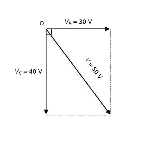
An AC source of 50 V (rms) is connected to a series RC circuit. The voltage across the resistor is 30 V (rms). What is the voltage across the capacitor?

Diagram for question 5: Alternating Current
Show answer
Option (B) is correct.

Explanation: In a series AC circuit, voltages across components add as phasors (not algebraically), since V_R and V_C are 90° out of phase.

By the phasor relation: V_source² = V_R² + V_C²

∴ V_C² = V_source² − V_R² = (50)² − (30)² = 2500 − 900 = 1600

∴ V_C = 40 V
Q6MCQ1 mark

A household electric iron is rated 1000 W, 220 V (rms). It is connected to a 220 V (rms), 50 Hz AC supply. A student makes the following statements about this circuit:

(i) The peak voltage across the iron is 220 V.
(ii) The average power consumed by the iron over a full cycle is 1000 W.
(iii) The resistance of the heating element of the iron is 48.4 Ω.
(iv) Since AC current reverses direction every half-cycle, the net energy delivered to the iron over a complete cycle is zero.

Which of the following correctly identifies the TRUE and FALSE statements?

Show answer
Option (c) is correct.

Explanation:

For an AC supply, the peak voltage V₀ and rms voltage V_rms are related by:

V₀ = √2 × V_rms

∴ V₀ = √2 × 220 = 1.414 × 220 ≈ 311 V

So statement (i) is FALSE — the peak voltage is 311 V, not 220 V.

For a purely resistive device (like an electric iron), the average power consumed over a full cycle is:

P_avg = V_rms × I_rms = V²_rms / R

Since the iron is rated 1000 W at 220 V (rms), it is designed to consume exactly 1000 W under these conditions.
∴ Statement (ii) is TRUE.

The resistance of the heating element is found from:

P = V²_rms / R
→ R = V²_rms / P = (220)² / 1000 = 48400 / 1000 = 48.4 Ω

∴ Statement (iii) is TRUE.

Although AC current reverses direction, the heating effect (power dissipation) depends on I²R, which is always positive regardless of current direction. Energy is delivered to the resistive element in both half-cycles.
∴ Statement (iv) is FALSE — net energy delivered per cycle is NOT zero; it equals P_avg × T = 1000 × (1/50) = 20 J per cycle.

∴ Only statements (ii) and (iii) are true; (i) and (iv) are false — Option (c) is correct.
Q7MCQ1 mark

In an AC circuit, the power factor is 1. Which of the following correctly describes this circuit?

Show answer
Option (C) is correct.

Explanation: Power factor is defined as cosφ = R/Z, where φ is the phase angle between voltage and current.

For power factor = 1, cosφ = 1 → φ = 0°, which requires X<sub>L</sub> − X<sub>C</sub> = 0.

In a purely resistive circuit, X<sub>L</sub> = X<sub>C</sub> = 0, so Z = R, giving cosφ = R/R = 1.

∴ The circuit contains only a resistor.
Q8MCQ1 mark

In a series LCR circuit connected to an ac source, at resonance the impedance of the circuit is:

Show answer
Option (B) is correct.

Explanation: For a series LCR circuit, impedance Z = √(R² + (X<sub>L</sub> − X<sub>C</sub>)²).

At resonance, X<sub>L</sub> = X<sub>C</sub>, so (X<sub>L</sub> − X<sub>C</sub>) = 0.

∴ Z = R (minimum, purely resistive).
Q9Short Answer2 marks

Define the term 'power factor' of an AC circuit. Write its value for a purely inductive circuit.

Show answer
Power factor of an AC circuit is defined as the ratio of average (true) power consumed to the apparent power (virtual power) in the circuit.

Formula: cos φ = R/Z, where φ is the phase difference between voltage and current.

For a purely inductive circuit: the current lags behind the voltage by φ = 90°.

∴ Power factor = cos 90° = 0
Q10Short Answer2 marks

In a series LCR circuit, the inductive reactance is twice the capacitive reactance, and the resistance R = 10 Ω. Find (i) the phase difference between the voltage and the current, and (ii) the power factor of the circuit. Given: X_L = 2X_C and X_C = 10 Ω.

Show answer
For a series LCR circuit, the phase angle φ is given by:

tanφ = (X_L − X_C) / R

Given: X_C = 10 Ω, X_L = 2X_C = 20 Ω, R = 10 Ω.

Substituting:

tanφ = (20 − 10) / 10 = 10 / 10 = 1

∴ φ = π/4 radian (voltage leads current, since X_L > X_C).

(ii) Impedance Z = √(R² + (X_L − X_C)²) = √(10² + 10²) = √200 = 10√2 Ω

Power factor cosφ = R / Z = 10 / (10√2)

∴ Power factor = 1/√2 ≈ 0.707
Q11Short Answer2 marks

A series LCR circuit has resistance R = 6 Ω, inductive reactance X_L = 17 Ω, and capacitive reactance X_C = 9 Ω. Calculate (i) the impedance of the circuit and (ii) the power factor, when connected to an ac source.

Show answer
(i) The impedance of a series LCR circuit is given by:
Z = √(R² + (X_L − X_C)²)

Substituting the given values (R = 6 Ω, X_L = 17 Ω, X_C = 9 Ω):
Z = √((6)² + (17 − 9)²)
Z = √(36 + 64)
Z = √100

∴ Z = 10 Ω

(ii) The power factor of a series LCR circuit is given by:
cosφ = R / Z

Substituting values:
cosφ = 6 / 10

∴ Power factor, cosφ = 0.6
Q12Short Answer3 marks

A series LCR circuit is connected to an ac source of rms voltage 100 V. The resistance, inductive reactance, and capacitive reactance in the circuit are R = 60 Ω, X_L = 110 Ω, and X_C = 30 Ω respectively.
(a) Calculate the impedance of the circuit.
(b) Find the rms current flowing through the circuit.
(c) Determine the average power dissipated in the circuit.

Show answer
(a) Impedance of a series LCR circuit:

By the formula for impedance of a series LCR circuit,

Z = √(R² + (X_L − X_C)²)

Substituting the given values:

Z = √((60)² + (110 − 30)²)
= √((60)² + (80)²)
= √(3600 + 6400)
= √10000

∴ Z = 100 Ω

(b) RMS current in the circuit:

By Ohm's law for ac circuits,

I_rms = V_rms / Z

Substituting:

I_rms = 100 V / 100 Ω

∴ I_rms = 1 A

(c) Average power dissipated:

The average power in a series LCR circuit is given by

P_avg = V_rms · I_rms · cos φ

where the power factor is

cos φ = R / Z = 60 / 100 = 0.6

Substituting:

P_avg = 100 V × 1 A × 0.6

∴ P_avg = 60 W

(Note: Power is dissipated only in the resistor; the inductor and capacitor are purely reactive elements and consume no average power.)
Q13Short Answer3 marks

A smart home automation engineer is testing an audio crossover circuit. She connects an inductor L = 2/π H, a capacitor C = 50/π μF, and a resistor R = 100 Ω in series to a variable-frequency AC source of fixed rms voltage V_rms = 200 V.

(a) At what angular frequency ω₀ does the circuit resonate? Calculate the rms current at resonance.
(b) At a different frequency, the engineer observes that X_L = 300 Ω and X_C = 100 Ω. Calculate the impedance Z and the power factor cos φ of the circuit at this frequency.
(c) The engineer then wishes to make the circuit 'wattless' — i.e., zero average power dissipated. State the condition required and explain why, even though rms current may be non-zero, average power can be zero.

Show answer
MARKING SCHEME (4 marks total)

━━━━━━━━━━━━━━━━━━━━━━━━━━━━━━
PART (a) — Resonant frequency and rms current at resonance [1½ marks]
━━━━━━━━━━━━━━━━━━━━━━━━━━━━━━

At resonance, the inductive reactance equals the capacitive reactance:

X_L = X_C → ω₀L = 1/(ω₀C) → ω₀ = 1/√(LC)

Substituting L = 2/π H and C = 50/π μF = 50/π × 10⁻⁶ F:

LC = (2/π) × (50/π × 10⁻⁶)
= 100/(π² × 10⁶)
= 100/(π² × 10⁶)

ω₀ = 1/√(LC)
= 1/√(100/(π² × 10⁶))
= 1 × π × 10³ / 10
= π × 10² / 1

Let us compute carefully:

√(LC) = √(100/(π² × 10⁶))
= 10/(π × 10³)
= 10⁻²/π

∴ ω₀ = 1/(10⁻²/π) = 100π rad s⁻¹

At resonance, Z = R (since X_L − X_C = 0):

I_rms = V_rms / R = 200 / 100

∴ ω₀ = 100π rad s⁻¹ and I_rms (at resonance) = 2 A

━━━━━━━━━━━━━━━━━━━━━━━━━━━━━━
PART (b) — Impedance and power factor at a different frequency [1½ marks]
━━━━━━━━━━━━━━━━━━━━━━━━━━━━━━

For a series LCR circuit, the impedance is:

Z = √( R² + (X_L − X_C)² )

Given: X_L = 300 Ω, X_C = 100 Ω, R = 100 Ω

X_L − X_C = 300 − 100 = 200 Ω

Z = √( (100)² + (200)² )
= √( 10000 + 40000 )
= √50000
= 100√5

∴ Z = 100√5 ≈ 224 Ω

Power factor:

cos φ = R/Z = 100 / (100√5) = 1/√5

∴ cos φ = 1/√5 ≈ 0.45

(Circuit is inductive since X_L > X_C, voltage leads current.)

━━━━━━━━━━━━━━━━━━━━━━━━━━━━━━
PART (c) — Condition and explanation for wattless current [1 mark]
━━━━━━━━━━━━━━━━━━━━━━━━━━━━━━

Condition: The circuit must be purely reactive (either purely inductive or purely capacitive), so that the phase difference φ between voltage and current is 90°, i.e., R = 0 (or effectively, the resistive component of impedance is zero).

Average power: P_avg = V_rms I_rms cos φ

When φ = 90°, cos φ = 0, therefore P_avg = 0.

Physical reason: In a purely reactive circuit, energy is stored in the electric field of the capacitor and the magnetic field of the inductor during one half-cycle and is completely returned to the source during the next half-cycle. There is no net energy dissipated per cycle even though the rms current I_rms is non-zero. The current is therefore called 'wattless current'.
Q14Short Answer3 marks

A city electricity board supplies ac power at 220 V (rms), 50 Hz to a small workshop. The workshop owner connects three components in series to this supply: an inductor of inductance L = 2/π H, a capacitor of capacitance C = 200/π μF, and a resistor of resistance R = 100 Ω.

(i) Calculate the inductive reactance X_L and the capacitive reactance X_C of the circuit.
(ii) Find the impedance Z of the series LCR circuit.
(iii) Calculate the rms current flowing through the circuit.
(iv) The workshop owner wants maximum power to be delivered to the resistor. Suggest ONE change he can make to the circuit (keeping the supply frequency fixed) and justify your answer using the concept of resonance.

Show answer
Given:
V<sub>rms</sub> = 220 V, f = 50 Hz, L = 2/π H, C = 200/π μF = 200/π × 10<sup>−6</sup> F, R = 100 Ω.

Angular frequency: ω = 2πf = 2π × 50 = 100π rad s<sup>−1</sup>.

(i) Inductive reactance X<sub>L</sub> and capacitive reactance X<sub>C</sub>:

By definition, X<sub>L</sub> = ωL
→ X<sub>L</sub> = 100π × (2/π)
∴ X<sub>L</sub> = 200 Ω

By definition, X<sub>C</sub> = 1/ωC
→ X<sub>C</sub> = 1 / (100π × 200/π × 10<sup>−6</sup>)
→ X<sub>C</sub> = 1 / (100π × 200 × 10<sup>−6</sup> / π)
→ X<sub>C</sub> = 1 / (0.02)
∴ X<sub>C</sub> = 50 Ω

(ii) Impedance of the series LCR circuit:

For a series LCR circuit, Z = √(R<sup>2</sup> + (X<sub>L</sub> − X<sub>C</sub>)<sup>2</sup>)
→ Z = √((100)<sup>2</sup> + (200 − 50)<sup>2</sup>)
→ Z = √(10000 + (150)<sup>2</sup>)
→ Z = √(10000 + 22500)
→ Z = √32500
→ Z = 50√13 Ω ≈ 180.3 Ω
∴ Z ≈ 180 Ω

(iii) Rms current in the circuit:

By Ohm's law for ac circuits, I<sub>rms</sub> = V<sub>rms</sub> / Z
→ I<sub>rms</sub> = 220 / 180.3
∴ I<sub>rms</sub> ≈ 1.22 A

(iv) Condition for maximum power delivery:

The average power dissipated in a series LCR circuit is P<sub>avg</sub> = V<sub>rms</sub> I<sub>rms</sub> cosφ, where the power factor cosφ = R/Z.
Power is maximum when cosφ = 1, i.e., Z = R (minimum impedance). This occurs at resonance when X<sub>L</sub> = X<sub>C</sub>.

At resonance: X<sub>L</sub> = X<sub>C</sub>
→ ωL = 1/ωC
→ Required: X<sub>C</sub> = X<sub>L</sub> = 200 Ω
→ New C = 1/(ω × X<sub>L</sub>) = 1/(100π × 200) = 1/(20000π) F ≈ 15.9 μF

Suggestion: The workshop owner should replace the 200/π μF capacitor with a capacitor of capacitance C = 1/(ω²L) = 1/((100π)<sup>2</sup> × 2/π) = 1/(20000π) F ≈ 15.9 μF.

Justification: At resonance, X<sub>L</sub> = X<sub>C</sub>, so the net reactance is zero and the impedance reduces to Z = R (its minimum value). The power factor becomes cosφ = R/R = 1, and the power delivered to the resistor P = V<sub>rms</sub><sup>2</sup>/R is maximum.
Q15Short Answer3 marks

A solar power plant uses an ideal step-up transformer to feed electricity into the national grid. The primary coil has 200 turns connected to a 400 V (rms) AC source, and the secondary coil has 10,000 turns.

(i) What is the output (secondary) voltage of this transformer?

(ii) If the power delivered to the primary is 8 kW, find the current in the secondary coil.

(iii) An engineer suggests that using a higher turns ratio (step-up) transformer reduces transmission losses. Using the expression for power loss, explain why this is so.

(iv) In practice, the transformer core is made of laminated sheets rather than a solid iron block. Give one reason why.

Show answer
(i) Finding the secondary voltage:

For an ideal transformer, the voltage ratio equals the turns ratio:

V<sub>s</sub>/V<sub>p</sub> = N<sub>s</sub>/N<sub>p</sub>

Substituting: V<sub>s</sub>/400 = 10000/200

∴ V<sub>s</sub> = 400 × 50 = 20,000 V

∴ Output (secondary) voltage = 20,000 V (20 kV).

(ii) Finding the secondary current:

For an ideal transformer, P<sub>in</sub> = P<sub>out</sub> (energy is conserved).

P = V<sub>s</sub> × I<sub>s</sub>

Substituting: 8000 = 20000 × I<sub>s</sub>

∴ I<sub>s</sub> = 8000/20000 = 0.4 A

∴ Current in the secondary coil = 0.4 A.

(iii) Explanation of reduced transmission losses:

The power lost in a transmission line of resistance R is given by:

P<sub>loss</sub> = I²R

A step-up transformer increases the voltage (V<sub>s</sub> >> V<sub>p</sub>). Since power P = VI is constant, a higher transmission voltage means a proportionally lower transmission current I. Because P<sub>loss</sub> = I²R, even a small reduction in I causes a large reduction in power loss (loss ∝ I²). Therefore, stepping up the voltage significantly reduces resistive heating losses in transmission cables.

(iv) Reason for laminated core:

A solid iron core would allow large induced (eddy) currents to circulate within it, causing significant energy loss as heat (P = I²R). Laminating the core into thin insulated sheets increases the electrical resistance to these circulating currents, thereby greatly reducing eddy current losses and improving the efficiency of the transformer.
Q16Short Answer3 marks

A physics student sets up a series LCR circuit in the laboratory using a resistor R = 40 Ω, an inductor L = 200 mH, and a capacitor C = 50 μF, connected to an AC source of peak voltage 200 V. While taking measurements, the student notices that the ammeter reads maximum current when the source frequency is adjusted to a particular value f₀.

(i) Calculate the resonant frequency f₀ of this circuit.
(ii) At resonance, calculate the impedance Z of the circuit and the rms current through it.
(iii) The student now increases the source frequency slightly above f₀. State, with reason, whether the circuit becomes predominantly inductive or capacitive.
(iv) If the student replaces the resistor with one of resistance 80 Ω (keeping L and C the same), how does the resonant frequency f₀ change? Justify your answer.

Show answer
(i) At resonance, X<sub>L</sub> = X<sub>C</sub>, so ω<sub>0</sub>L = 1/ω<sub>0</sub>C → ω<sub>0</sub> = 1/√(LC)

ω<sub>0</sub> = 1/√(200×10<sup>−3</sup> × 50×10<sup>−6</sup>)
= 1/√(10<sup>−5</sup>)
= 1/(3.16×10<sup>−3</sup>)
= 316.2 rad s<sup>−1</sup>

∴ f<sub>0</sub> = ω<sub>0</sub>/2π = 316.2/6.28 ≈ 50.3 Hz ≈ 50 Hz

(ii) At resonance, X<sub>L</sub> = X<sub>C</sub>, so:

Z = √(R² + (X<sub>L</sub> − X<sub>C</sub>)²) = √(R² + 0) = R

∴ Z = 40 Ω

V<sub>rms</sub> = V<sub>peak</sub>/√2 = 200/√2 ≈ 141.4 V

I<sub>rms</sub> = V<sub>rms</sub>/Z = 141.4/40

∴ I<sub>rms</sub> ≈ 3.54 A

(iii) The circuit becomes predominantly inductive.

Reason: For a series LCR circuit, X<sub>L</sub> = ωL and X<sub>C</sub> = 1/ωC. When frequency f is increased above f<sub>0</sub>, X<sub>L</sub> increases (X<sub>L</sub> ∝ ω) while X<sub>C</sub> decreases (X<sub>C</sub> ∝ 1/ω). Therefore X<sub>L</sub> > X<sub>C</sub>, and the net reactance (X<sub>L</sub> − X<sub>C</sub>) becomes positive — the circuit behaves as predominantly inductive.

(iv) The resonant frequency f<sub>0</sub> does NOT change.

Justification: The resonant frequency is given by f<sub>0</sub> = 1/(2π√(LC)). It depends only on the inductance L and capacitance C of the circuit, and is completely independent of the resistance R. Since L and C are unchanged, f<sub>0</sub> remains the same at ≈ 50 Hz even after replacing R = 40 Ω with R = 80 Ω.
Q17Short Answer3 marks

A student sets up a series LCR circuit in the laboratory with the following components: a resistor of resistance R = 40 Ω, an inductor of inductance L = 80 mH, and a capacitor of capacitance C = 125 μF. The circuit is connected to an AC source of rms voltage 220 V and variable frequency.

(i) At what frequency will the circuit be in resonance? [1 mark]
(ii) Calculate the impedance and rms current at resonance. [1 mark]
(iii) The student notices that at resonance the voltage across the inductor is much greater than the supply voltage. Explain why this does NOT violate energy conservation. [1 mark]
(iv) If the frequency of the AC source is now increased well above the resonance frequency, state with reason whether the circuit becomes predominantly capacitive or inductive. [1 mark]

Show answer
(i) Finding the Resonance Frequency:

At resonance, X<sub>L</sub> = X<sub>C</sub>, which gives ω<sub>0</sub> = 1/√(LC).

→ ω<sub>0</sub> = 1/√(80 × 10<sup>−3</sup> × 125 × 10<sup>−6</sup>)
→ ω<sub>0</sub> = 1/√(10<sup>−5</sup>) = 1/(10<sup>−2.5</sup>)
→ ω<sub>0</sub> = 1/√(10000 × 10<sup>−9</sup>)

Let us compute: LC = 80 × 10<sup>−3</sup> × 125 × 10<sup>−6</sup> = 10000 × 10<sup>−9</sup> = 10<sup>−5</sup>
→ ω<sub>0</sub> = 1/√(10<sup>−5</sup>) = 10<sup>2.5</sup> = 100√10 rad s<sup>−1</sup>

∴ f<sub>0</sub> = ω<sub>0</sub>/2π = 100√10/(2π) ≈ 316.2/(6.283) ≈ 50.3 Hz

∴ Resonance frequency f<sub>0</sub> ≈ 50.3 Hz (or equivalently ω<sub>0</sub> = 100√10 ≈ 316 rad s<sup>−1</sup>).

(ii) Impedance and rms Current at Resonance:

At resonance, X<sub>L</sub> = X<sub>C</sub>, so Z = √(R² + (X<sub>L</sub> − X<sub>C</sub>)²) = √(R² + 0) = R.

→ Z = R = 40 Ω

By Ohm's law for AC: I<sub>rms</sub> = V<sub>rms</sub>/Z
→ I<sub>rms</sub> = 220/40 = 5.5 A

∴ At resonance, Z = 40 Ω and I<sub>rms</sub> = 5.5 A.

(iii) Why Voltage Across L (or C) Exceeds Supply Voltage — No Violation of Energy Conservation:

At resonance, the voltage across the inductor V<sub>L</sub> = I<sub>rms</sub> × X<sub>L</sub> and the voltage across the capacitor V<sub>C</sub> = I<sub>rms</sub> × X<sub>C</sub> are equal in magnitude but exactly 180° out of phase with each other. Therefore they cancel each other completely in the series circuit. Only the voltage across R equals the supply voltage (V<sub>R</sub> = I<sub>rms</sub>R = V<sub>rms</sub>). The large voltages across L and C are reactive — they store and release energy alternately (no net power consumed by an ideal L or C). Since the net power dissipated equals I<sub>rms</sub>²R (only by R), energy conservation is fully satisfied.

(iv) Nature of Circuit at Frequency Well Above Resonance:

The circuit becomes predominantly inductive.

Reason: For a series LCR circuit, X<sub>L</sub> = ωL increases with frequency while X<sub>C</sub> = 1/ωC decreases with frequency. When ω >> ω<sub>0</sub>, X<sub>L</sub> >> X<sub>C</sub>, so (X<sub>L</sub> − X<sub>C</sub>) > 0. The net reactance is inductive, the current lags the voltage, and the circuit behaves as a predominantly inductive circuit.
Q18Short Answer3 marks

A ceiling fan in a household is connected to a 230 V, 50 Hz AC supply. The fan motor has a resistance R = 20 Ω and an inductance L = 0.4 H connected in series.

(i) Calculate the impedance of the fan circuit.
(ii) Calculate the current drawn by the fan.
(iii) Calculate the power factor of the circuit.
(iv) A capacitor of capacitance C is now connected in series with the fan circuit to improve the power factor to unity. What value of C is required?

Show answer
(i) Impedance of the fan circuit:

For a series RL circuit, the impedance is given by:

Z = √(R² + X<sub>L</sub>²)

where X<sub>L</sub> = ωL = 2πνL

Substituting: X<sub>L</sub> = 2π × 50 × 0.4 = 125.6 Ω ≈ 126 Ω

Z = √((20)² + (126)²) = √(400 + 15876) = √16276

∴ Z ≈ 127.6 Ω ≈ 128 Ω

(ii) Current drawn by the fan:

By Ohm's law for AC circuits: I<sub>rms</sub> = V<sub>rms</sub> / Z

Substituting: I<sub>rms</sub> = 230 / 127.6

∴ I<sub>rms</sub> ≈ 1.80 A

(iii) Power factor of the circuit:

For a series RL circuit, power factor is:

cosφ = R / Z

Substituting: cosφ = 20 / 127.6

∴ cosφ ≈ 0.157

The circuit is largely inductive (cosφ << 1), meaning most power drawn is wattless (reactive).

(iv) Value of C required for power factor = 1 (unity):

For power factor to become unity, the circuit must be at resonance, i.e., X<sub>C</sub> = X<sub>L</sub>.

At resonance: X<sub>C</sub> = X<sub>L</sub> = 126 Ω

Since X<sub>C</sub> = 1 / ωC:

C = 1 / (ω × X<sub>C</sub>) = 1 / (2π × 50 × 126)

C = 1 / (39584)

∴ C ≈ 2.53 × 10<sup>−5</sup> F ≈ 25.3 μF

Physical significance: Adding this capacitor cancels the inductive reactance of the fan motor, bringing the voltage and current in phase (φ = 0°). The circuit now draws only real (useful) power, reducing energy wastage — this is how power factor correction is applied in household and industrial appliances.
Q19Short Answer3 marks

A series LCR circuit consists of a resistor R = 200 Ω, an inductor L = 2/π H, and a capacitor C = 50/π μF connected across an ac source v = 200√2 sin(100π t) V.
(a) Find the impedance of the circuit.
(b) Calculate the average power consumed by the circuit.
(c) What is the power factor of the circuit? State whether the circuit is predominantly inductive or capacitive.

Show answer
Given: R = 200 Ω, L = 2/π H, C = 50/π μF = 50/π × 10⁻⁶ F, v = 200√2 sin(100π t) V
∴ Peak voltage V₀ = 200√2 V, so V_rms = V₀/√2 = 200 V
Angular frequency ω = 100π rad s⁻¹

(a) Inductive reactance:
X_L = ωL = 100π × (2/π) = 200 Ω

Capacitive reactance:
X_C = 1/ωC = 1/(100π × 50/π × 10⁻⁶) = 1/(100π × 50 × 10⁻⁶/π)
= 1/(50 × 100 × 10⁻⁶) = 1/(5 × 10⁻³) = 200 Ω

Impedance:
Z = √(R² + (X_L − X_C)²)
Z = √((200)² + (200 − 200)²)
Z = √(40000 + 0)
∴ Z = 200 Ω

(b) Since X_L = X_C, the circuit is at resonance.
Rms current: I_rms = V_rms/Z = 200/200 = 1 A

Average power consumed:
P_avg = V_rms × I_rms × cos φ
At resonance, φ = 0° → cos φ = 1
P_avg = 200 × 1 × 1
∴ P_avg = 200 W

(c) Power factor:
cos φ = R/Z = 200/200
∴ cos φ = 1

Since X_L = X_C, the circuit is at resonance — it is neither predominantly inductive nor capacitive; it behaves as a purely resistive circuit at this frequency.
Q20Short Answer3 marks

A student sets up an LCR series circuit in the school laboratory. She uses an inductor of inductance L = 0.5 H, a capacitor of capacitance C = 200 μF, and a resistor of resistance R = 40 Ω, connected to an AC source of variable frequency. She observes that at a certain frequency f₀, the current in the circuit becomes maximum.

(i) What is the condition for maximum current in a series LCR circuit? Name this phenomenon.

(ii) Calculate the frequency f₀ at which maximum current flows.

(iii) The student now doubles the inductance (L becomes 2L) while keeping C and R unchanged. How does the resonant frequency change? (Give the ratio f₀_new / f₀_old.)

(iv) At the original resonant frequency f₀, the student measures the terminal voltage across the capacitor and finds it is 150 V. What is the rms current in the circuit at resonance?

Show answer
(i) The condition for maximum current in a series LCR circuit is:

X<sub>L</sub> = X<sub>C</sub> i.e., ωL = 1/ωC

At this condition, the impedance Z = √(R² + (X<sub>L</sub> − X<sub>C</sub>)²) is minimum and equals R, so current I = V/R is maximum.

This phenomenon is called Electrical Resonance (Series Resonance).

(ii) At resonance: ω₀ = 1/√(LC)

∴ f₀ = 1 / (2π√(LC))

Substituting L = 0.5 H, C = 200 × 10<sup>−6</sup> F:

LC = 0.5 × 200 × 10<sup>−6</sup> = 1 × 10<sup>−4</sup> H·F

√(LC) = √(10<sup>−4</sup>) = 10<sup>−2</sup> s

f₀ = 1 / (2π × 10<sup>−2</sup>) = 100 / (2π)

∴ f₀ ≈ 15.9 Hz

(iii) New resonant frequency when L is doubled to 2L:

f₀_new = 1 / (2π√(2L · C))

f₀_new / f₀_old = √(LC) / √(2LC) = 1/√2

∴ f₀_new / f₀_old = 1/√2 ≈ 0.707

The resonant frequency decreases by a factor of 1/√2.

(iv) At resonance, X<sub>C</sub> = 1/ω₀C.

ω₀ = 2πf₀ = 2π × (100/2π) = 100 rad/s

X<sub>C</sub> = 1 / (ω₀C) = 1 / (100 × 200 × 10<sup>−6</sup>) = 1 / (0.02) = 50 Ω

The rms voltage across the capacitor: V<sub>C</sub> = I<sub>rms</sub> × X<sub>C</sub>

⇒ I<sub>rms</sub> = V<sub>C</sub> / X<sub>C</sub> = 150 / 50

∴ I<sub>rms</sub> = 3 A
Q21Short Answer3 marks

A power company transmits 10 kW of electrical power from a generating station at 250 V using a step-up transformer T₁ and a step-down transformer T₂ at the consumer end. The transmission line has a total resistance of 40 Ω.

(i) What voltage must T₁ step up to if the transmission line current is to be limited to 5 A?

(ii) Calculate the power lost in the transmission line.

(iii) A student claims: 'If we connect an inductor L and a capacitor C in series with the transmission line at resonance (ω₀ = 1/√(LC)), the power loss in the line will become zero because the net reactance is zero.' Evaluate this claim — is it correct or incorrect? Give a physical reason.

(iv) The step-down transformer T₂ at the consumer end has 2000 turns in its primary coil. If it delivers 250 V to consumers, how many turns does its secondary have? (Assume ideal transformers.)

Show answer
(i) By the transformer and power relation, the voltage to which T₁ must step up is found using:

P = V_line × I_line

V_line = P / I_line = (10 × 10³ W) / (5 A)

∴ V_line = 2000 V

T₁ must step up the voltage from 250 V to 2000 V.

(ii) By Joule's heating law, power lost in transmission line:

P_loss = I² R

P_loss = (5)² × 40

∴ P_loss = 1000 W = 1 kW

(iii) The student's claim is INCORRECT.

At resonance in a series LC circuit, the net reactance X_L − X_C = 0, so the impedance of the LC combination is zero. This means the LC branch offers no opposition to current flow, and the voltage across the LC series combination is zero.

However, the power loss in the transmission line occurs due to the RESISTANCE R of the line, not its reactance. Since resistance R is unchanged and the line current I = 5 A still flows through R, the power dissipated is P_loss = I²R = 1 kW, which is non-zero.

Adding an ideal LC series branch at resonance does not reduce the resistance of the line. Therefore, the power loss remains unchanged at 1 kW. The student's claim is physically incorrect — only reducing the line current (by stepping up voltage) reduces transmission loss, not adding a resonant LC circuit in series.

(iv) By the transformer turns ratio (ideal transformer):

V_s / V_p = N_s / N_p

The primary of T₂ receives the stepped-up line voltage (minus the drop across the line).

Voltage drop across line = I × R = 5 × 40 = 200 V

∴ Voltage across primary of T₂ = 2000 − 200 = 1800 V

Using turns ratio:
N_s / N_p = V_s / V_p = 250 / 1800

N_s = N_p × (250 / 1800) = 2000 × (250 / 1800)

N_s = 2000 × 5/36 ≈ 277.8 ≈ 278 turns

∴ The secondary of T₂ has approximately 278 turns.
Q22Short Answer3 marks

A city substation receives electricity at 11 kV (rms) from a distant power plant. It uses an ideal step-down transformer (Transformer T1) to reduce the voltage to 220 V (rms) for domestic use. The primary coil of T1 has 5000 turns.

(i) How many turns does the secondary coil of T1 have?

(ii) If the domestic load draws a total power of 44 kW, find the rms current in the primary (high-voltage) winding of T1.

(iii) The same substation also supplies a small factory through a second ideal transformer (Transformer T2) that steps 11 kV down to 440 V. The factory's load has a resistance of 9.68 Ω and an inductive reactance of 7.26 Ω. Calculate the power factor of the factory's load and state whether it is leading or lagging.

Show answer
MARKING SCHEME (Total: 4 marks)

━━━━━━━━━━━━━━━━━━━━━━━━━━━━
Part (i) — Number of secondary turns [1 mark]
━━━━━━━━━━━━━━━━━━━━━━━━━━━━

For an ideal transformer, the turns ratio equals the voltage ratio:

Ns / Np = Vs / Vp

Substituting:

Ns / 5000 = 220 / 11000

Ns = 5000 × (220 / 11000)

Ns = 5000 × (1/50)

∴ Ns = 100 turns

━━━━━━━━━━━━━━━━━━━━━━━━━━━━
Part (ii) — Primary rms current [1 mark]
━━━━━━━━━━━━━━━━━━━━━━━━━━━━

For an ideal transformer, input power equals output power:

P = Vp × Ip

Substituting:

44 × 10³ = 11 × 10³ × Ip

Ip = (44 × 10³) / (11 × 10³)

∴ Ip = 4 A

(This illustrates the key advantage of high-voltage transmission — only 4 A flows in the primary at 11 kV, greatly reducing transmission losses compared to 200 A that would flow at 220 V.)

━━━━━━━━━━━━━━━━━━━━━━━━━━━━
Part (iii) — Power factor of the factory load [2 marks]
━━━━━━━━━━━━━━━━━━━━━━━━━━━━

The factory load is a series RL circuit (resistive + inductive).

For a series RL circuit, the impedance is:

Z = √(R² + XL²)

Substituting R = 9.68 Ω, XL = 7.26 Ω:

Z = √( (9.68)² + (7.26)² )

Z = √( 93.7024 + 52.7076 )

Z = √146.41

Z = 12.1 Ω

The power factor is:

cos φ = R / Z

cos φ = 9.68 / 12.1

∴ cos φ = 0.8 (lagging, since the load is inductive — current lags behind voltage)
Q23Short Answer3 marks

A solar power plant uses an ideal step-up transformer to transmit electrical energy over long distances. The primary coil has 200 turns and is connected to an AC source of 400 V (rms). The secondary coil has 10,000 turns. The transmission line has a total resistance of 50 Ω. The plant delivers power to a load at the receiving end.

(i) Calculate the output (secondary) voltage of the transformer.
(ii) If the power supplied to the primary is 8 kW, find the rms current in the transmission line (secondary current).
(iii) Calculate the power loss in the transmission line.
(iv) Why is it more efficient to transmit electrical power at high voltage rather than at low voltage? Give a reason based on the formula for power loss.

Show answer
(i) Voltage ratio of an ideal transformer:

By the transformer equation,

V<sub>s</sub> / V<sub>p</sub> = N<sub>s</sub> / N<sub>p</sub>

Substituting values:

V<sub>s</sub> = V<sub>p</sub> × (N<sub>s</sub> / N<sub>p</sub>) = 400 × (10,000 / 200)

∴ V<sub>s</sub> = 400 × 50 = 20,000 V = 20 kV

──────────────────────────────────────

(ii) Rms current in the transmission line (secondary current):

For an ideal transformer, power input = power output.

P = V<sub>s</sub> × I<sub>s</sub>

→ I<sub>s</sub> = P / V<sub>s</sub> = 8000 / 20,000

∴ I<sub>s</sub> = 0.4 A

──────────────────────────────────────

(iii) Power loss in the transmission line:

Power loss P<sub>loss</sub> = I<sub>s</sub><sup>2</sup> × R

Substituting values:

P<sub>loss</sub> = (0.4)<sup>2</sup> × 50

P<sub>loss</sub> = 0.16 × 50

∴ P<sub>loss</sub> = 8 W

──────────────────────────────────────

(iv) Reason for transmitting power at high voltage:

The power loss in a transmission line is given by:

P<sub>loss</sub> = I<sup>2</sup>R = (P / V)<sup>2</sup> × R

For a fixed power P transmitted, increasing the voltage V reduces the current I in proportion. Since P<sub>loss</sub> ∝ I<sup>2</sup>, even a small reduction in current causes a large reduction in power loss. Therefore, transmitting at high voltage greatly reduces resistive heating losses in the line, making transmission far more efficient.
Q24Short Answer3 marks

A power transmission company generates electricity at 11 kV (rms) and steps it up using a transformer T₁ (turns ratio Nₚ : Nₛ = 1 : 20) before sending it over long-distance cables of total resistance 40 Ω. At the consumer end, a step-down transformer T₂ reduces the voltage back to 220 V (rms) for domestic use. The total power delivered to consumers is 440 kW.

(i) Find the rms voltage at the output of transformer T₁.
(ii) Find the rms current in the transmission cable.
(iii) Calculate the power lost as heat in the transmission cables.
(iv) What percentage of the total power generated is lost in transmission? Hence comment on why high-voltage transmission is preferred.

Show answer
(i) Finding the rms voltage at the output of T₁:

For an ideal transformer, the voltage transformation ratio is:

V<sub>s</sub> / V<sub>p</sub> = N<sub>s</sub> / N<sub>p</sub>

Given: V<sub>p</sub> = 11 kV = 11,000 V, N<sub>s</sub>/N<sub>p</sub> = 20

V<sub>s</sub> = V<sub>p</sub> × (N<sub>s</sub>/N<sub>p</sub>) = 11,000 × 20

∴ V<sub>s</sub> (rms voltage at output of T₁) = 2,20,000 V = 220 kV

(ii) Finding the rms current in the transmission cable:

For an ideal transformer, power is conserved:

P = V<sub>s</sub> × I<sub>cable</sub> (since P = V<sub>rms</sub> I<sub>rms</sub> at unity power factor for transmission line)

The power fed into the line = power delivered to consumers = 440 kW = 4,40,000 W

I<sub>cable</sub> = P / V<sub>s</sub> = 4,40,000 / 2,20,000

∴ I<sub>cable</sub> = 2 A

(iii) Calculating power lost in transmission cables:

By Joule's heating law, power loss in cables:

P<sub>loss</sub> = I<sub>cable</sub><sup>2</sup> × R

P<sub>loss</sub> = (2)<sup>2</sup> × 40

P<sub>loss</sub> = 4 × 40

∴ P<sub>loss</sub> = 160 W

(iv) Percentage power loss and inference:

Total power generated = Power delivered + Power lost = 4,40,000 + 160 = 4,40,160 W ≈ 4,40,160 W

% loss = (P<sub>loss</sub> / P<sub>generated</sub>) × 100

% loss = (160 / 4,40,160) × 100

∴ % loss ≈ 0.036 % (extremely small)

Inference: Since P<sub>loss</sub> = I<sup>2</sup>R, stepping up the voltage by a large factor reduces the transmission current proportionally (I = P/V), thereby reducing I<sup>2</sup>R losses drastically. This is why high-voltage (high-tension) transmission over long distances is preferred — it minimises energy loss and improves efficiency of power delivery.
Q25Short Answer3 marks

A physics laboratory has set up an experimental LCR series circuit for students to analyse. The circuit is connected to an AC source of EMF ε = 200 sin(100πt) V. The circuit parameters are: resistance R = 40 Ω, inductance L = 0.5 H, and capacitance C = 200 μF.

(i) Identify the angular frequency (ω) of the source and calculate the inductive reactance (X_L) and capacitive reactance (X_C).

(ii) Calculate the impedance (Z) of the circuit and the peak current (I₀).

(iii) A student claims: 'If we remove the capacitor from this circuit, the current in the circuit will increase because there will be one less component opposing the flow of current.' Is the student's claim correct? Justify with calculation.

(iv) The same AC source is now connected to a pure capacitor of capacitance C = 200 μF. A classmate says that the average power consumed by the capacitor over a full cycle is equal to the peak power divided by 2. Is this correct? Give reason.

Show answer
Given: ε = 200 sin(100πt) V, R = 40 Ω, L = 0.5 H, C = 200 μF = 200 × 10⁻⁶ F

(i) From the expression ε = 200 sin(ωt), comparing:
∴ ω = 100π rad s⁻¹

Inductive reactance: X_L = ωL
→ X_L = 100π × 0.5 = 50π ≈ 157 Ω

Capacitive reactance: X_C = 1/ωC
→ X_C = 1/(100π × 200 × 10⁻⁶) = 1/(0.02π) = 50/π ≈ 15.9 Ω

∴ X_L ≈ 157 Ω, X_C ≈ 15.9 Ω

(ii) Impedance of LCR series circuit:
Z = √(R² + (X_L − X_C)²)
→ Z = √((40)² + (157 − 15.9)²)
→ Z = √(1600 + (141.1)²)
→ Z = √(1600 + 19909) = √21509 ≈ 146.7 Ω

∴ Z ≈ 147 Ω

Peak voltage V₀ = 200 V
Peak current: I₀ = V₀/Z
→ I₀ = 200/147 ≈ 1.36 A

∴ I₀ ≈ 1.36 A

(iii) The student's claim is INCORRECT.

Without the capacitor, the circuit becomes a pure RL series circuit.
New impedance: Z' = √(R² + X_L²)
→ Z' = √((40)² + (157)²)
→ Z' = √(1600 + 24649) = √26249 ≈ 162 Ω

New peak current: I₀' = V₀/Z' = 200/162 ≈ 1.23 A

Since Z' (≈ 162 Ω) > Z (≈ 147 Ω), removing the capacitor INCREASES the impedance and therefore DECREASES the current (1.23 A < 1.36 A).

Physical reason: In this circuit X_L > X_C, so the capacitor partially cancels the inductive reactance, reducing the net impedance. Removing the capacitor eliminates this partial cancellation, making the circuit more reactive (not less), and the current decreases.

∴ The student's claim is incorrect — the current decreases from ≈ 1.36 A to ≈ 1.23 A when the capacitor is removed.

(iv) The classmate's statement is INCORRECT.

For a pure capacitor connected to an AC source, the current leads the voltage by a phase angle φ = 90°.

Average power: P_avg = V_rms × I_rms × cos φ
→ P_avg = V_rms × I_rms × cos 90°
→ P_avg = V_rms × I_rms × 0 = 0 W

A pure capacitor is a lossless (reactive) element. It stores energy during one quarter cycle and returns it completely during the next quarter cycle. Over a complete cycle, the net energy consumed is zero.

The classmate's formula (P_avg = P_peak/2) applies only to a pure resistor (where φ = 0°), not to a pure capacitor.

∴ The average power consumed by the pure capacitor over a full cycle is zero (not P_peak/2). The current through it is called wattless current.
Q26Short Answer3 marks

A factory uses an AC power supply of 240 V (rms), 50 Hz to run a motor modelled as a series LCR circuit with resistance R = 40 Ω, inductance L = 0.3 H, and capacitance C = 50 μF.

(i) Calculate the impedance Z of the circuit.
(ii) Find the rms current drawn from the supply.
(iii) The factory engineer notices that if she removes the capacitor from the circuit, the current drawn decreases significantly. Explain why this happens using the concept of resonance, and state what condition would give maximum current in the original LCR circuit.

Show answer
(i) Impedance of the series LCR circuit:

By the formula for impedance:

Z = √(R² + (X_L − X_C)²)

where X_L = ωL and X_C = 1/ωC, with ω = 2πf = 2π × 50 = 100π rad s⁻¹.

X_L = ωL = 100π × 0.3 = 30π ≈ 94.25 Ω

X_C = 1/ωC = 1/(100π × 50 × 10⁻⁶) = 1/(100π × 5 × 10⁻⁵) = 1/(5π × 10⁻³) = 200/π ≈ 63.66 Ω

X_L − X_C = 94.25 − 63.66 = 30.59 Ω

Z = √((40)² + (30.59)²)
= √(1600 + 935.7)
= √2535.7

∴ Z ≈ 50.4 Ω

(ii) Rms current drawn from the supply:

By Ohm's law for AC circuits:

I_rms = V_rms / Z = 240 / 50.4

∴ I_rms ≈ 4.76 A

(iii) Explanation using resonance:

In the original LCR circuit, the capacitive reactance X_C partially cancels the inductive reactance X_L (since X_L > X_C here), reducing the net reactance and therefore reducing Z below what it would be with only R and L.

When the capacitor is removed, the circuit becomes a series RL circuit with impedance:

Z_RL = √(R² + X_L²) = √((40)² + (94.25)²) = √(1600 + 8883.1) = √10483.1 ≈ 102.4 Ω

This is much larger than Z ≈ 50.4 Ω of the LCR circuit, so the current decreases significantly — from ≈ 4.76 A to only 240/102.4 ≈ 2.34 A.

Condition for maximum current (resonance):

At resonance, X_L = X_C, so the net reactance is zero and Z = Z_min = R.

This occurs at the resonant frequency:

ω₀ = 1/√(LC) = 1/√(0.3 × 50 × 10⁻⁶) = 1/√(1.5 × 10⁻⁵) ≈ 258 rad s⁻¹

∴ The original LCR circuit would draw maximum current I_max = V_rms/R = 240/40 = 6 A when the supply frequency is set to ω₀ = 1/√(LC) ≈ 258 rad s⁻¹ (≈ 41 Hz), at which point impedance equals R = 40 Ω alone.
Q27Short Answer3 marks

A student sets up a series LCR circuit connected to an ac source of peak voltage V₀ = 200 V and frequency f = 50 Hz. She measures the following component values: resistance R = 40 Ω, inductance L = 0.3 H, and capacitance C = 200 μF.

(i) Calculate the inductive reactance X_L and capacitive reactance X_C of the circuit at the given frequency.

(ii) Determine the impedance Z of the circuit and the peak current I₀ through it.

(iii) The student now wants to achieve resonance. She keeps R and L fixed and adjusts C. Find the value of C required for resonance.

(iv) At resonance, how does the power factor of the circuit change compared to its value in part (ii)? Justify your answer.

Show answer
(i) By definition of reactances in an LCR circuit:

X_L = ωL = 2πfL
→ X_L = 2π × 50 × 0.3
→ X_L = 2π × 15 = 30π ≈ 94.2 Ω

X_C = 1/ωC = 1/(2πfC)
→ X_C = 1/(2π × 50 × 200 × 10⁻⁶)
→ X_C = 1/(2π × 0.01) = 1/(0.02π) ≈ 15.9 Ω

∴ X_L ≈ 94.2 Ω and X_C ≈ 15.9 Ω

(ii) The impedance of a series LCR circuit is:
Z = √(R² + (X_L − X_C)²)
→ (X_L − X_C) = 94.2 − 15.9 = 78.3 Ω
→ Z = √((40)² + (78.3)²)
→ Z = √(1600 + 6130.9) = √7730.9
∴ Z ≈ 87.9 Ω

Peak current:
I₀ = V₀/Z
→ I₀ = 200/87.9
∴ I₀ ≈ 2.28 A

(iii) At resonance, X_L = X_C, so:
ω₀L = 1/(ω₀C)
→ C = 1/(ω₀²L) = 1/((2πf)²L)
→ C = 1/((2π × 50)² × 0.3)
→ C = 1/(4π² × 2500 × 0.3)
→ C = 1/(4 × 9.87 × 750)
→ C = 1/29610
∴ C ≈ 3.38 × 10⁻⁵ F ≈ 33.8 μF

(iv) The power factor is defined as:
cosφ = R/Z

In part (ii): cosφ = 40/87.9 ≈ 0.455 (less than 1; circuit is predominantly inductive).

At resonance: X_L = X_C, so Z = √(R² + 0²) = R = 40 Ω.
→ cosφ = R/Z = 40/40 = 1

∴ At resonance, the power factor becomes 1 (unity), its maximum possible value. This is because the net reactance is zero — the inductive and capacitive reactances cancel each other completely — leaving only pure resistance in the circuit. The current and voltage are in phase (φ = 0°), and the circuit absorbs maximum power from the source.
Q28Short Answer3 marks

A radio engineer is designing a series LCR circuit to be used as a band-pass filter in an FM receiver. The circuit has inductance L = 2.5 mH, capacitance C = 10 nF, and resistance R = 25 Ω. The circuit is driven by an ac source of peak voltage 50 V.

(i) Calculate the resonant frequency f₀ of this circuit.

(ii) At resonance, calculate the peak current I₀ and the peak voltage across the capacitor V_C.

(iii) The engineer finds that V_C is much larger than the source voltage. Name this phenomenon and state the condition under which it becomes more pronounced. Also write the expression for the quality factor Q of a series LCR circuit in terms of L, C, and R.

(iv) If the resistance R is halved (keeping L and C unchanged), state with justification what happens to (a) the resonant frequency, and (b) the sharpness of resonance (Q-factor).

Show answer
(i) Finding the Resonant Frequency

At resonance, X_L = X_C, so the resonant angular frequency is:

ω₀ = 1/√(LC)

Substituting L = 2.5 × 10⁻³ H, C = 10 × 10⁻⁹ F:

ω₀ = 1/√(2.5 × 10⁻³ × 10 × 10⁻⁹)
= 1/√(2.5 × 10⁻¹¹)
= 1/(5 × 10⁻⁶)
= 2 × 10⁵ rad s⁻¹

∴ f₀ = ω₀/2π = (2 × 10⁵)/(2π)

∴ f₀ ≈ 3.18 × 10⁴ Hz ≈ 31.8 kHz

──────────────────────────────────────
(ii) Peak Current and Peak Voltage Across the Capacitor at Resonance

At resonance, Z = R (impedance is minimum and purely resistive).

∴ I₀ = V₀/R = 50/25

∴ I₀ = 2 A

The reactance of the capacitor at resonance:

X_C = 1/(ω₀C) = 1/(2 × 10⁵ × 10 × 10⁻⁹)
= 1/(2 × 10⁻³)
= 500 Ω

Peak voltage across the capacitor:

V_C = I₀ × X_C = 2 × 500

∴ V_C = 1000 V

──────────────────────────────────────
(iii) Phenomenon and Quality Factor

The phenomenon is called Voltage Resonance (or Resonance in a series LCR circuit). The peak voltage across the capacitor (and inductor) exceeds the source voltage because the reactive voltages V_L and V_C are equal in magnitude but opposite in phase and cancel each other, while the current is maximum.

Condition for it to become more pronounced: It becomes more pronounced when the resistance R is small (R → 0), i.e., when the circuit has a high quality factor.

The quality factor Q is defined as the ratio of the voltage across L (or C) to the voltage across R at resonance:

Q = (1/R)√(L/C)

∴ Q = (ω₀L)/R = 1/(ω₀CR)

──────────────────────────────────────
(iv) Effect of Halving R

(a) Resonant frequency when R is halved:

The resonant frequency of a series LCR circuit is:

ω₀ = 1/√(LC)

This expression is independent of R. Since L and C are unchanged, the resonant frequency f₀ remains the same.

∴ f₀ is unchanged.

(b) Sharpness of resonance (Q-factor) when R is halved:

Q = (1/R)√(L/C)

Since Q ∝ 1/R, halving R doubles Q.

∴ The sharpness of resonance increases (the resonance curve becomes narrower and taller), meaning the circuit becomes more selective — it responds to a narrower band of frequencies around f₀.
Q29Short Answer3 marks

A student in a school science exhibition sets up a series LCR circuit using an inductor of inductance 0.5 H, a capacitor of 50 μF, and a resistor of 40 Ω, all connected to a 200 V (rms) ac source of variable frequency.

(i) At what frequency will the circuit be in resonance?
(ii) Calculate the impedance and the rms current in the circuit at resonance.
(iii) The student notices that the voltage across the inductor at resonance is much larger than the supply voltage of 200 V. Is this possible? Justify your answer briefly.

Show answer
CBSE Marking Scheme (Total: 4 marks)

(i) Resonance Frequency [1 mark]

At resonance, inductive reactance equals capacitive reactance:
X_L = X_C
ω₀L = 1/ω₀C
→ ω₀ = 1/√(LC)

Substituting: L = 0.5 H, C = 50 μF = 50 × 10⁻⁶ F
ω₀ = 1/√(0.5 × 50 × 10⁻⁶)
= 1/√(25 × 10⁻⁶)
= 1/(5 × 10⁻³)
= 200 rad s⁻¹

∴ Resonant frequency f₀ = ω₀/2π = 200/2π ≈ 31.8 Hz

(ii) Impedance and Current at Resonance [1½ marks]

At resonance, X_L = X_C, so they cancel.
Formula: Z = √(R² + (X_L − X_C)²)
→ At resonance: Z = R = 40 Ω

∴ Z = 40 Ω

Rms current:
I_rms = V_rms/Z = 200/40

∴ I_rms = 5 A

(iii) Voltage Across Inductor Greater Than Supply — The Paradox [1½ marks]

Voltage across inductor at resonance:
V_L = I_rms × X_L = I_rms × ω₀L
= 5 × 200 × 0.5
= 500 V

Yes, V_L = 500 V > 200 V (supply voltage). This is indeed possible.

Justification: At resonance, V_L and V_C are equal in magnitude but exactly 180° out of phase with each other. They therefore cancel each other out completely. The net voltage across the LC combination is zero, and the entire supply voltage (200 V) appears only across the resistor. The individual voltages V_L and V_C can be very large (their ratio V_L/V_rms = ω₀L/R = Q, the quality factor), yet their vector (phasor) sum is zero — so there is no violation of Kirchhoff's voltage law.
Q30Short Answer3 marks

A power transmission engineer is designing a circuit to deliver electrical energy from a substation to an industrial unit. The substation supplies a sinusoidal AC voltage of peak value 200√2 V at a frequency of 50 Hz. The industrial unit requires a series LCR circuit load with R = 40 Ω, L = 0.3 H, and C = 1/(300π²) F connected across the supply.

(i) Calculate the angular frequency ω₀ at which electrical resonance occurs in the circuit. Is the supply frequency equal to the resonance frequency? Justify.

(ii) At the supply frequency of 50 Hz, calculate the impedance Z of the circuit.

(iii) The engineer wants to achieve maximum power transfer (resonance condition) by replacing the capacitor with a new one, keeping L and R unchanged. What should be the capacitance of the new capacitor?

(iv) At resonance, what is the average power consumed by the circuit? Also state what happens to the power factor at resonance and why.

Show answer
Given: Peak voltage V₀ = 200√2 V, so V<sub>rms</sub> = V₀/√2 = 200 V; f = 50 Hz; R = 40 Ω; L = 0.3 H; C = 1/(300π²) F.

(i) At electrical resonance, X<sub>L</sub> = X<sub>C</sub>, i.e., ω₀L = 1/ω₀C
→ ω₀ = 1/√(LC)
→ ω₀ = 1/√(0.3 × 1/(300π²))
→ ω₀ = 1/√(0.3/(300π²))
→ ω₀ = 1/√(1/(1000π²))
→ ω₀ = √(1000π²) = 10π√10 ≈ 99.3 rad s⁻¹

Supply angular frequency ω = 2πf = 2π × 50 = 100π ≈ 314 rad s⁻¹.

Since ω ≠ ω₀ (314 ≠ 99.3 rad s⁻¹), the supply frequency is NOT equal to the resonance frequency. The circuit operates off-resonance at the given supply frequency.

(ii) At ω = 100π rad s⁻¹:
X<sub>L</sub> = ωL = 100π × 0.3 = 30π ≈ 94.25 Ω
X<sub>C</sub> = 1/ωC = 1/(100π × 1/(300π²)) = 300π²/(100π) = 3π ≈ 9.42 Ω

Impedance Z = √(R² + (X<sub>L</sub> − X<sub>C</sub>)²)
→ Z = √((40)² + (30π − 3π)²)
→ Z = √(1600 + (27π)²)
→ Z = √(1600 + 729π²)
→ Z = √(1600 + 7193.1)
→ Z = √8793.1
∴ Z ≈ 93.8 Ω

(iii) For resonance at supply frequency ω = 100π rad s⁻¹:
Resonance condition: ω²LC_new = 1
→ C_new = 1/(ω²L)
→ C_new = 1/((100π)² × 0.3)
→ C_new = 1/(10000π² × 0.3)
→ C_new = 1/(3000π²)
∴ C_new = 1/(3000π²) F ≈ 3.38 × 10⁻⁵ F (≈ 33.8 μF)

(iv) At resonance, Z = R = 40 Ω (since X<sub>L</sub> = X<sub>C</sub>, they cancel).
I<sub>rms</sub> = V<sub>rms</sub>/Z = 200/40 = 5 A
Average power P<sub>avg</sub> = V<sub>rms</sub> × I<sub>rms</sub> × cosφ
At resonance, phase angle φ = 0° ⟹ cosφ = 1 (power factor = 1, unity).
→ P<sub>avg</sub> = V<sub>rms</sub> × I<sub>rms</sub> × 1 = 200 × 5
∴ P<sub>avg</sub> = 1000 W = 1 kW

The power factor becomes unity (cosφ = 1) at resonance because X<sub>L</sub> = X<sub>C</sub>, so the net reactance is zero. The voltage and current are in phase, and all the electrical energy supplied is dissipated as heat in the resistance R — no energy is stored/returned by L or C on net.

Want unlimited practice on Alternating Current?

The full ClearSteps bank has 44+ reviewed questions on this chapter alone — with step-wise solutions, difficulty levels, and progress tracking. Verify your WhatsApp number and your free trial starts right here.

CBSE · CLASS 12
🎟️14-day free trial · code PRAC auto-applied
Mobile Number
+91
OTP will be sent to your WhatsApp

⭐ Trusted by 12,000+ students across India

Alternating Current — Class 12 Physics Practice Questions