ClearStepsCLEARSTEPS AI
Teacher Login →Student Login →

Electromagnetic Induction: Class 12 Physics Practice Questions

30 original exam-pattern questions with full answers, matched to the current CBSE Class 12 paper design, including case-based questions. Attempt each question before opening the answer — or start a free 14-day trial ↓ for the full bank.

Q1Case-based4 marks

Power plants and residential areas are rarely located near each other. Electrical energy must be transmitted over long distances through conducting cables that have resistance. Transformers — devices based on the principle of mutual induction — are used to step voltages up and down to make transmission efficient. An ideal transformer obeys: V<sub>s</sub>/V<sub>p</sub> = N<sub>s</sub>/N<sub>p</sub> and, for an ideal transformer, V<sub>p</sub>I<sub>p</sub> = V<sub>s</sub>I<sub>s</sub>. Power lost in a cable of resistance R carrying current I is P<sub>loss</sub> = I²R.

A small town is connected to a power plant 20 km away. The plant generates 10 kW of power at 500 V. To reduce transmission losses, a step-up transformer at the plant boosts the voltage to 10,000 V before transmission through cables of total resistance 50 Ω. A step-down transformer at the town end then reduces the voltage for domestic use.

(i) Calculate the current in the transmission line.
(ii) Calculate the power lost in the transmission cables.
(iii) If the power lost in transmission must be reduced to one-fourth of the value found in part (ii), by what factor must the transmission voltage be increased (keeping the generated power constant)?
(iv) State ONE reason why AC is preferred over DC for long-distance power transmission.

Show answer
(i) Finding the transmission-line current:

By the relation for an ideal transformer, the power transmitted equals the power generated (ideal step-up transformer at the plant).

P = V<sub>trans</sub> × I<sub>trans</sub>

∴ I<sub>trans</sub> = P / V<sub>trans</sub> = 10,000 W / 10,000 V

∴ I<sub>trans</sub> = 1 A

(ii) Power lost in transmission cables:

By P<sub>loss</sub> = I²R, where R = 50 Ω and I = 1 A,

P<sub>loss</sub> = (1)<sup>2</sup> × 50

∴ P<sub>loss</sub> = 50 W

(iii) Factor by which transmission voltage must be increased:

For constant generated power P, the transmission current I ∝ 1/V<sub>trans</sub>.

Since P<sub>loss</sub> = I²R ∝ 1/V<sub>trans</sub>², reducing P<sub>loss</sub> to one-fourth requires I to be halved, which requires V<sub>trans</sub> to be doubled.

∴ The transmission voltage must be increased by a factor of 2 (i.e., to 20,000 V).

(iv) AC is preferred over DC for long-distance transmission because the voltage of AC can be easily stepped up or stepped down using transformers (which work on the principle of electromagnetic induction and require a changing — i.e., alternating — current). Higher transmission voltage means lower current and hence much lower I²R losses in the cables.
Q2Case-based4 marks

A school science club builds a hand-cranked AC generator using a rectangular coil rotating inside a uniform magnetic field. The coil has 200 turns, each of area 0.04 m², rotating at 5 rev/s in a magnetic field of 0.05 T. The students observe that the LED connected to the generator glows when the coil rotates and they explore how changing parameters affects brightness.

A school science club builds a simple hand-cranked generator to light an LED during a power outage. The generator consists of a rectangular coil of 200 turns, each of area 0.04 m², rotating in a uniform magnetic field of 0.05 T. The coil completes 5 full revolutions every second.

(i) Write the expression for the instantaneous EMF induced in the rotating coil. Identify the quantity that represents the peak (maximum) EMF.

(ii) Calculate the peak EMF produced by this generator.

(iii) The student now doubles the rotation speed (to 10 rev/s) to make the LED brighter. By what factor does the peak EMF change? Justify your answer using the expression from part (i).

(iv) Instead of increasing speed, the student suggests replacing the coil with one having double the number of turns (400 turns) while keeping everything else the same (at the original 5 rev/s). Compare this modification with doubling the speed: which gives the same peak EMF, and why?

Show answer
(i) Expression for instantaneous EMF:

By Faraday's law of electromagnetic induction, when a coil of N turns and area A rotates with angular velocity ω in a uniform magnetic field B, the magnetic flux through the coil at time t is:

Φ = NBA cos(ωt)

By Faraday's law, E = −dΦ/dt

∴ E = NBAω sin(ωt)

This can be written as: E = E₀ sin(ωt)

where E₀ = NBAω is the peak (maximum) EMF.

The quantity E₀ = NBAω represents the peak EMF. [1 mark]

(ii) Calculation of peak EMF:

Given: N = 200 turns, A = 0.04 m², B = 0.05 T, f = 5 rev/s

Angular velocity: ω = 2πf = 2π × 5 = 10π rad/s

Using the formula: E₀ = NBAω

Substituting values:

E₀ = 200 × 0.05 × 0.04 × 10π

E₀ = 200 × 0.05 × 0.04 × 31.4

E₀ = 200 × 0.002 × 31.4

E₀ = 200 × 0.0628

∴ E₀ = 12.56 V ≈ 12.6 V [1 mark]

(iii) Effect of doubling rotation speed:

From E₀ = NBAω and ω = 2πf:

E₀ ∝ ω ∝ f (since N, B, A are constant)

When f is doubled from 5 rev/s to 10 rev/s:

New ω′ = 2π × 10 = 20π rad/s

New E₀′ = NBAω′ = 200 × 0.05 × 0.04 × 20π = 25.12 V

∴ The peak EMF doubles (increases by a factor of 2).

Justification: Since E₀ = NBAω and ω is directly proportional to f, doubling the frequency doubles the angular velocity, which directly doubles the peak EMF. [1 mark]

(iv) Comparison of the two modifications:

Original peak EMF: E₀ = NBAω = 200 × 0.05 × 0.04 × 10π = 12.56 V

Modification 1 — Double the speed (f = 10 rev/s, N = 200):
E₀′ = 200 × 0.05 × 0.04 × 20π = 25.12 V

Modification 2 — Double the turns (N = 400, f = 5 rev/s):
E₀″ = 400 × 0.05 × 0.04 × 10π = 25.12 V

∴ Both modifications give the same peak EMF (25.12 V), i.e., both double the peak EMF.

Reason: Since E₀ = NBAω, the peak EMF is directly proportional to both N and ω. Doubling either N (number of turns) or ω (angular velocity, by doubling frequency) has an identical effect — it multiplies E₀ by the same factor of 2. The two modifications are therefore equivalent in terms of peak EMF produced. [1 mark]
Q3Case-based4 marks

A rectangular coil of length 20 cm and width 10 cm, having 50 turns, is placed flat on a horizontal table in a uniform magnetic field directed vertically upward. The field decreases uniformly from 0.8 T to 0.2 T in 0.3 s. The coil has a resistance of 5 Ω.

A rectangular coil of length 20 cm and width 10 cm, having 50 turns, is placed flat on a horizontal table. A uniform magnetic field directed vertically upward passes through the coil. A student observes that the magnetic field decreases uniformly from 0.8 T to 0.2 T in 0.3 s.

(i) State Faraday's law of electromagnetic induction.
(ii) Calculate the magnitude of the induced emf in the coil during this interval.
(iii) If the resistance of the coil is 5 Ω, find the induced current in the coil.
(iv) The student then tilts the coil so that its plane makes an angle of 30° with the direction of the magnetic field (i.e., the normal to the coil makes 60° with B⃗). If the same rate of change of flux through the coil (as calculated above) is maintained, state whether the induced emf will increase, decrease, or remain the same, and give a reason.

Show answer
(i) Faraday's Law of Electromagnetic Induction states that: The magnitude of the induced emf in a circuit is directly proportional to the rate of change of magnetic flux linked with the circuit.
Mathematically: E = −N dΦ/dt

(ii) By Faraday's law, the induced emf is given by:
E = N × (ΔΦ/Δt) = N × A × (ΔB/Δt)

Given:
N = 50 turns
A = length × width = 20 × 10⁻² m × 10 × 10⁻² m = 0.02 m²
ΔB/Δt = (0.8 − 0.2)/0.3 = 0.6/0.3 = 2 T s⁻¹

Substituting:
E = 50 × 0.02 m² × 2 T s⁻¹
E = 50 × 0.04
∴ E = 2 V

(iii) By Ohm's law, induced current I = E/R
I = 2 V / 5 Ω
∴ I = 0.4 A

(iv) The induced emf will remain the same.
Reason: By Faraday's law, the induced emf depends on the rate of change of magnetic flux (E = −N dΦ/dt), not on the orientation of the coil. Since the problem states that the same rate of change of flux through the coil is maintained even after tilting, the induced emf remains E = 2 V, unchanged.
Q4Case-based4 marks

A student is designing a simple electromagnetic security sensor. A small rectangular coil of 200 turns, each of area 4 × 10⁻³ m², is connected to a sensitive galvanometer. The coil is placed in a uniform magnetic field of magnitude 0.05 T such that the plane of the coil is parallel to the field. A person walking through a doorway causes the coil to rotate by 90° (so that the plane becomes perpendicular to the field) in a time of 0.1 s.

A student is designing a simple electromagnetic security sensor. A small rectangular coil of 200 turns, each of area 4 × 10⁻³ m², is connected to a sensitive galvanometer. The coil is placed in a uniform magnetic field of magnitude 0.05 T such that the plane of the coil is parallel to the field. A person walking through a doorway causes the coil to rotate by 90° (so that the plane becomes perpendicular to the field) in a time of 0.1 s.

(i) What is the initial magnetic flux linked with the coil?
(ii) What is the final magnetic flux linked with the coil after rotation?
(iii) Calculate the magnitude of the average EMF induced in the coil during this rotation.
(iv) The student now replaces the coil with one having the same area but only 100 turns, and the same rotation happens in 0.05 s. Will the induced EMF increase, decrease, or remain the same? Justify your answer with a calculation.

Show answer
MARKING SCHEME (1 + 1 + 1 + 1 = 4 marks)

(i) Initial magnetic flux linked with the coil:

Magnetic flux is defined as Φ = NBA cosθ, where θ is the angle between the magnetic field B⃗ and the normal to the plane of the coil.

When the plane of the coil is parallel to B⃗, the normal to the coil is perpendicular to B⃗, so θ = 90°.

→ Φ_initial = NBA cos 90° = NBA × 0 = 0

∴ Initial magnetic flux = 0 Wb

(ii) Final magnetic flux linked with the coil:

After rotating 90°, the plane of the coil is perpendicular to B⃗, so the normal to the coil is parallel to B⃗, giving θ = 0°.

→ Φ_final = NBA cos 0° = NBA
→ Φ_final = 200 × 0.05 × 4 × 10⁻³
→ Φ_final = 200 × 2 × 10⁻⁴
→ Φ_final = 4 × 10⁻² Wb

∴ Final magnetic flux = 4 × 10⁻² Wb = 0.04 Wb

(iii) Magnitude of average induced EMF:

By Faraday's law of electromagnetic induction, the magnitude of the average induced EMF is:

|E| = |ΔΦ / Δt| = |(Φ_final − Φ_initial)| / Δt

→ |E| = |(4 × 10⁻² − 0)| / 0.1
→ |E| = 4 × 10⁻² / 0.1

∴ Magnitude of average induced EMF = 0.4 V

(iv) Effect of replacing the coil:

New coil: N' = 100 turns, A' = 4 × 10⁻³ m² (same), B = 0.05 T, Δt' = 0.05 s.

The same rotation (plane parallel → plane perpendicular to B⃗) means:
ΔΦ' = N'BA' cos 0° − N'BA' cos 90° = N'BA'
→ ΔΦ' = 100 × 0.05 × 4 × 10⁻³ = 2 × 10⁻² Wb

|E'| = ΔΦ' / Δt' = (2 × 10⁻²) / 0.05

∴ |E'| = 0.4 V

The induced EMF remains the same (0.4 V). Although the number of turns is halved (reducing ΔΦ by half), the time taken is also halved, so the two effects cancel each other exactly.
Q5MCQ1 mark

The self-inductance of a long air-cored solenoid is L. If the number of turns per unit length is doubled (keeping its length and cross-sectional area unchanged), the new self-inductance becomes:
(a) L/2
(b) L
(c) 2L
(d) 4L

Show answer
Option (d) is correct.

Explanation: The self-inductance of a long solenoid is given by L = μ₀n²Al, where n is the number of turns per unit length, A is the cross-sectional area, and l is the length.

Since L ∝ n², doubling n (i.e., n → 2n) gives:

L′ = μ₀(2n)²Al = 4μ₀n²Al = 4L.

∴ The new self-inductance = 4L.
Q6MCQ1 mark

The SI unit of mutual inductance is:

Show answer
Option (C) is correct.

Explanation: Mutual inductance M is defined by the relation E₂ = −M dI₁/dt. Rearranging, M = E₂ / (dI₁/dt), giving SI unit Volt·second/Ampere = Henry (H). Hence the SI unit of mutual inductance is Henry (H).
Q7MCQ1 mark

The magnetic flux linked with a coil changes from 12 Wb to 4 Wb in 2 s. What is the magnitude of the average emf induced in the coil?

Show answer
Option (A) is correct.

Explanation: By Faraday's law of electromagnetic induction, the magnitude of average induced emf is given by |E| = |ΔΦ/Δt|.

Here ΔΦ = 12 − 4 = 8 Wb and Δt = 2 s.

∴ |E| = 8/2 = 4 V.
Q8MCQ1 mark

A coil has a self-inductance of 20 mH. The current through it changes at a uniform rate of 500 A/s. What is the magnitude of the emf induced in the coil?

Show answer
Option (b) is correct.

Explanation: By Faraday's law of electromagnetic induction, the self-induced emf is given by |E| = L |dI/dt|.

Here L = 20 mH = 20 × 10⁻³ H and dI/dt = 500 A/s.

∴ |E| = 20 × 10⁻³ × 500 = 10 V.
Q9MCQ1 mark

A straight conducting rod of length 0.5 m is moved with a velocity of 4 m/s perpendicular to a uniform magnetic field of 0.2 T directed into the plane of the paper. What is the magnitude of the induced emf in the rod?

Show answer
Option (B) is correct.

Explanation: By Faraday's law of electromagnetic induction, the motional emf induced in a rod of length l moving with velocity v perpendicular to a magnetic field B is given by:

ε = Blv

Substituting the given values:
ε = 0.2 × 0.5 × 4

∴ ε = 0.4 V
Q10MCQ1 mark

A circular coil is moved rapidly out of a uniform magnetic field region. The induced emf in the coil depends on:

Show answer
Option (B) is correct.

Explanation: By Faraday's law of electromagnetic induction, the induced emf in a coil is given by:

ε = −N dΦ/dt

Thus, the induced emf depends on the rate of change of magnetic flux (dΦ/dt) linked with the coil, not on the total flux, resistance, or number of turns alone.
Q11Short Answer2 marks

A solenoid of length 50 cm, cross-sectional area 4 cm², and having 200 turns carries a current of 5 A. Calculate the magnetic flux linked with each turn of the solenoid and the self-inductance of the solenoid.

Show answer
The magnetic field inside a solenoid is given by:

B = μ₀nI, where n = N/l = 200/0.50 = 400 turns m⁻¹

Substituting values:
B = (4π×10⁻⁷) × 400 × 5
B = 4π×10⁻⁷ × 2000
B = 8π×10⁻⁴ T ≈ 2.51×10⁻³ T

Magnetic flux linked with each turn:
Φ = B × A = 8π×10⁻⁴ × 4×10⁻⁴
∴ Φ = 32π×10⁻⁸ Wb ≈ 1.005×10⁻⁶ Wb ≈ 1.0×10⁻⁶ Wb

Self-inductance of the solenoid:
L = NΦ/I = (200 × 32π×10⁻⁸) / 5
L = (6400π×10⁻⁸) / 5
∴ L = 1280π×10⁻⁸ H ≈ 4.02×10⁻⁵ H ≈ 4.0×10⁻⁵ H
Q12Short Answer2 marks

A rectangular coil of N turns, each of area A, is placed in a uniform magnetic field B⃗. The coil is rotated with a constant angular velocity ω about an axis perpendicular to the field, starting from the position where the plane of the coil is perpendicular to B⃗ (i.e., flux is maximum at t = 0).
(i) Write the expression for the magnetic flux Φ linked with the coil at time t.
(ii) Hence, derive the expression for the instantaneous emf induced in the coil.

Show answer
(i) Expression for magnetic flux:

At t = 0, the plane of the coil is perpendicular to B⃗, so the angle between the area vector (normal to the coil) and B⃗ is zero. As the coil rotates with angular velocity ω, the angle at time t is ωt.

By definition, Φ = NBA cos(ωt)

∴ Φ = NBA cos ωt

(ii) Derivation of induced emf:

By Faraday's law of electromagnetic induction, the induced emf is:

e = −dΦ/dt

→ e = −d(NBA cos ωt)/dt

→ e = −NBA × (−sin ωt) × ω

∴ e = NBAω sin ωt

This can be written as e = e₀ sin ωt, where e₀ = NBAω is the peak (maximum) emf.
Q13Short Answer2 marks

A rectangular coil of N turns, each of area A, is held stationary in a uniform magnetic field B⃗. The magnetic field varies with time as B = B₀ sin ωt, where B₀ and ω are constants and the plane of the coil is perpendicular to B⃗ at all times. (i) Write an expression for the emf induced in the coil. (ii) At what instant(s) in the first cycle (0 ≤ t ≤ 2π/ω) is the induced emf maximum?

Show answer
By Faraday's law of electromagnetic induction, the induced emf is:

ε = −dΦ/dt

The magnetic flux linked with the coil:
Φ = N·B·A = NBA₀ sin ωt (since plane of coil ⊥ B⃗, so θ = 0°, cos θ = 1)

→ ε = −d(NBA₀ sin ωt)/dt

∴ ε = −NBA₀ω cos ωt

(i) The induced emf is: ε = −NBA₀ω cos ωt

(ii) The magnitude of emf is maximum when |cos ωt| = 1,
i.e., ωt = 0, π, 2π

∴ The induced emf is maximum at t = 0, t = π/ω, and t = 2π/ω in the first cycle.
Q14Short Answer3 marks

A rectangular conducting loop of length 40 cm and width 25 cm has a resistance of 8 Ω. It is placed in a region where the magnetic field is directed perpendicular to the plane of the loop (into the page) and varies with time as B(t) = (0.5t² + 2t) T, where t is in seconds.

(i) Find the magnitude of the induced emf in the loop at t = 2 s.

(ii) Calculate the induced current in the loop at t = 2 s and state the direction of this current (clockwise or anticlockwise as viewed from the front).

(iii) A student claims: 'Since the resistance of the loop is fixed, doubling the area of the loop will always double the induced current, regardless of how B varies with time.' Analyse this claim. Is it always valid? Justify with reference to the expression for induced emf.

Show answer
Area of loop: A = 40 cm × 25 cm = 0.40 × 0.25 = 0.10 m²
Resistance: R = 8 Ω
Magnetic field: B(t) = (0.5t² + 2t) T (into the page)

─────────────────────────────────────
(i) Magnitude of induced emf at t = 2 s [1½ marks]
─────────────────────────────────────
By Faraday's law of electromagnetic induction:
The induced emf is
|ε| = |dΦ/dt| = A |dB/dt|

(Since the area is constant and B is uniform over the loop.)

Differentiating B(t) with respect to t:
dB/dt = d/dt (0.5t² + 2t) = t + 2

At t = 2 s:
dB/dt = 2 + 2 = 4 T s⁻¹

Substituting:
|ε| = A × |dB/dt| = 0.10 × 4

∴ |ε| = 0.4 V

─────────────────────────────────────
(ii) Induced current and its direction at t = 2 s [1½ marks]
─────────────────────────────────────
By Ohm's law:
I = |ε| / R = 0.4 / 8

∴ I = 0.05 A

Direction:
The magnetic flux into the page is increasing (since dB/dt > 0 at t = 2 s).
By Lenz's law, the induced current must oppose this increase — it must create a magnetic field out of the page inside the loop.
Using the right-hand rule, this requires the current to flow anticlockwise (as viewed from the front).

∴ The induced current is 0.05 A, flowing anticlockwise.

─────────────────────────────────────
(iii) Critical analysis of the student's claim [1 mark]
─────────────────────────────────────
The student's claim is NOT always valid.

The induced emf is given by Faraday's law:
|ε| = A |dB/dt|

The induced current is:
I = |ε| / R = (A |dB/dt|) / R

Doubling the area (A → 2A) gives:
I' = (2A |dB/dt|) / R = 2I

This shows the claim IS valid only when |dB/dt| is independent of position and uniform over the entire (enlarged) loop — i.e., the field varies uniformly with time everywhere.

However, if the magnetic field is non-uniform in space (so that B or dB/dt differs across the loop), then doubling the area does not simply double the flux change rate. In that case:
|ε| = |d/dt ∫∫ B⃗ · dA⃗| ≠ A × (dB/dt)
and the claim breaks down.

∴ The student's claim is valid only when the magnetic field is spatially uniform over the loop. For a spatially non-uniform field, doubling the area does not necessarily double the induced current.
Q15Short Answer3 marks

A rectangular conducting loop of dimensions 20 cm × 10 cm and resistance 5 Ω is placed in the plane of the page. A spatially uniform magnetic field B⃗, directed perpendicularly into the page, varies with time as B(t) = (0.2 + 4t²) T, where t is in seconds.

(i) Write the expression for the magnetic flux Φ through the loop at time t.
(ii) Calculate the magnitude of the induced emf in the loop at t = 2 s.
(iii) Find the magnitude of the induced current in the loop at t = 2 s.
(iv) A student claims that if the resistance of the loop is doubled to 10 Ω (keeping everything else the same), the induced emf at t = 2 s will also double. Is the student correct? Justify your answer in one sentence.

Show answer
(i) Magnetic flux through the loop:

By definition, Φ = B × A (since B⃗ is perpendicular to the plane of the loop, θ = 0°, cos 0° = 1).

Area A = 20 cm × 10 cm = 0.20 m × 0.10 m = 0.02 m²

∴ Φ(t) = B(t) × A = (0.2 + 4t²) × 0.02

∴ Φ(t) = (0.004 + 0.08t²) Wb

[1 mark]

(ii) Induced emf at t = 2 s:

By Faraday's law of electromagnetic induction:

|ε| = |dΦ/dt|

dΦ/dt = d/dt (0.004 + 0.08t²) = 0.16t

At t = 2 s:

|ε| = 0.16 × 2

∴ |ε| = 0.32 V

[1 mark]

(iii) Induced current at t = 2 s:

Using Ohm's law: I = ε / R

I = 0.32 / 5

∴ I = 0.064 A (= 64 mA)

[1 mark]

(iv) The student is incorrect.

Because the induced emf depends only on the rate of change of magnetic flux (ε = −dΦ/dt), which is determined entirely by B(t) and the area of the loop — both of which remain unchanged — the resistance of the loop has no effect on the induced emf; only the induced current would change (decrease) if resistance is doubled.

[1 mark]
Q16Short Answer3 marks

(a) State Faraday's law of electromagnetic induction. Write the significance of the negative sign in the expression for the induced emf.

(b) A rectangular loop of dimensions 8 cm × 5 cm is placed in a uniform magnetic field of 0.4 T directed perpendicular to the plane of the loop. The loop is pulled out of the field region in 0.2 s with uniform velocity. Calculate:
(i) the induced emf in the loop during this process.
(ii) the induced current, if the resistance of the loop is 4 Ω.

Show answer
(a) Faraday's Law of Electromagnetic Induction states that: the magnitude of the induced emf in a circuit is directly proportional to the rate of change of magnetic flux linked with it.

Mathematically: ε = −dΦ/dt

Significance of the negative sign: The negative sign indicates that the induced emf opposes the change in magnetic flux that causes it. This is a mathematical statement of Lenz's law, and reflects the law of conservation of energy — the induced current always acts to oppose the cause producing it.

(b) Given:
Length of loop l = 8 cm = 0.08 m
Breadth of loop b = 5 cm = 0.05 m
Magnetic field B = 0.4 T (perpendicular to plane of loop)
Time taken to pull out t = 0.2 s
Resistance R = 4 Ω

(i) Initial flux linked with the loop:
Φᵢ = B × A = B × l × b
Φᵢ = 0.4 × 0.08 × 0.05
Φᵢ = 1.6 × 10⁻³ Wb

Final flux (loop completely outside field):
Φ_f = 0

Change in flux: ΔΦ = Φ_f − Φᵢ = 0 − 1.6 × 10⁻³ = −1.6 × 10⁻³ Wb

Using Faraday's law:
|ε| = |ΔΦ / Δt| = 1.6 × 10⁻³ / 0.2

∴ Induced emf ε = 8 × 10⁻³ V = 8 mV

(ii) Using Ohm's law, I = ε / R
I = (8 × 10⁻³) / 4

∴ Induced current I = 2 × 10⁻³ A = 2 mA

(The direction of the induced current, by Lenz's law, is such as to oppose the decrease in flux — i.e., it flows in a direction to maintain the flux through the loop.)
Q17Short Answer3 marks

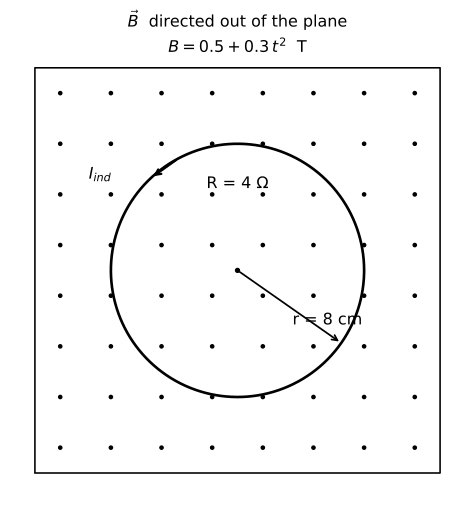
A circular conducting loop of radius 8 cm and resistance 4 Ω is placed in a uniform magnetic field B⃗ directed perpendicular to the plane of the loop. The magnetic field varies with time as B = 0.5 + 0.3t² (in Tesla, where t is in seconds).

(i) Find the expression for the induced EMF in the loop at any time t.
(ii) Calculate the induced EMF and the induced current in the loop at t = 3 s.
(iii) The loop is now replaced by a tightly wound coil of 50 turns of the same radius and resistance. Without any change in the magnetic field, determine the new induced current at t = 3 s.
(iv) In which direction will the induced current flow (clockwise or anticlockwise when viewed from the direction of B⃗) if B⃗ is increasing? Justify using Lenz's Law.

Diagram for question 17: Electromagnetic Induction
Show answer
Given: r = 8 cm = 0.08 m, R = 4 Ω, B = 0.5 + 0.3t² T, area A = πr² = π × (0.08)² = 2.011 × 10⁻³ m².

(i) By Faraday's Law of Electromagnetic Induction:

Faraday's Law states that the magnitude of the induced EMF in a loop is equal to the rate of change of magnetic flux through it:

ε = −dΦ/dt

Flux through the loop: Φ = B · A = (0.5 + 0.3t²) × πr²

→ dΦ/dt = dB/dt × A = (0.6t) × πr²

∴ |ε| = 0.6t × π × (0.08)²

∴ ε(t) = 0.6t × 2.011 × 10⁻³

∴ ε(t) = 1.207 × 10⁻³ t V (expression for induced EMF at time t)

(ii) At t = 3 s:

ε = 1.207 × 10⁻³ × 3

∴ ε = 3.62 × 10⁻³ V ≈ 3.6 × 10⁻³ V

Using Ohm's Law: I = ε / R

I = (3.62 × 10⁻³) / 4

∴ I = 9.0 × 10⁻⁴ A (≈ 0.9 mA)

(iii) For a coil of N = 50 turns, same radius, same resistance R_coil = 4 Ω (resistance of the coil as given):

The induced EMF becomes: ε_N = N × dΦ/dt = 50 × 1.207 × 10⁻³ × 3

∴ ε_N = 50 × 3.62 × 10⁻³ = 0.181 V

New induced current: I_N = ε_N / R_coil = 0.181 / 4

∴ I_N = 4.52 × 10⁻² A (≈ 45.2 mA)

(iv) Direction of induced current — by Lenz's Law:

Lenz's Law states that the direction of the induced current is such that it opposes the change in magnetic flux that caused it.

Since B⃗ is directed towards the observer (out of the plane, as viewed from the direction of B⃗) and is increasing, the induced current must create a magnetic field opposing this increase, i.e., directed into the plane (away from the observer).

By the right-hand rule, a magnetic field directed into the plane (away from observer) is produced by a current flowing clockwise.

∴ The induced current flows in the CLOCKWISE direction when viewed from the direction of B⃗.
Q18Short Answer3 marks

Derive an expression for the self-inductance of a long air-core solenoid of length l, cross-sectional area A, and total number of turns N. Hence, calculate the self-inductance of a solenoid having 500 turns, length 0.50 m, and cross-sectional area 4 × 10⁻⁴ m².

Show answer
Part (i) — Derivation of Self-Inductance of a Solenoid

By Faraday's law of electromagnetic induction, the self-inductance L of a coil is defined by:

NΦ = L I

where NΦ is the total magnetic flux linkage and I is the current through the coil.

Consider a long air-core solenoid of length l, cross-sectional area A, and total number of turns N.

Number of turns per unit length: n = N / l

By Ampere's circuital law, the uniform magnetic field inside the solenoid is:

B = μ₀ n I = μ₀ (N/l) I

Magnetic flux through one turn:

Φ = B · A = μ₀ (N/l) I · A

Total flux linkage:

NΦ = N · μ₀ (N/l) I · A = μ₀ N² A I / l

Using NΦ = L I:

∴ L = μ₀ N² A / l

Part (ii) — Numerical Calculation

Given: N = 500, l = 0.50 m, A = 4 × 10⁻⁴ m², μ₀ = 4π × 10⁻⁷ T m A⁻¹

Using L = μ₀ N² A / l:

L = (4π × 10⁻⁷) × (500)² × (4 × 10⁻⁴) / (0.50)

L = (4π × 10⁻⁷) × (2.5 × 10⁵) × (4 × 10⁻⁴) / (0.50)

L = (4π × 10⁻⁷) × (2.0 × 10²)

L = 4π × 10⁻⁷ × 200

L = 4 × 3.14 × 2 × 10⁻⁵

L = 25.12 × 10⁻⁵

∴ L ≈ 2.51 × 10⁻⁴ H
Q19Short Answer3 marks

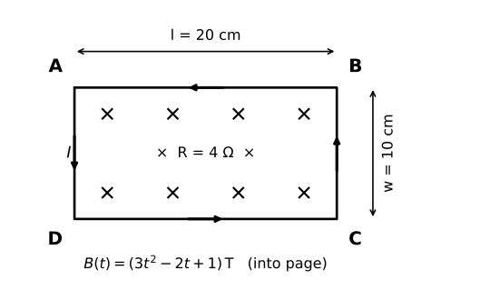
A rectangular conducting loop of length 20 cm and width 10 cm has a resistance of 4 Ω. It is placed in a plane perpendicular to a spatially uniform but time-varying magnetic field directed into the page. The magnetic field varies with time as B(t) = (3t² − 2t + 1) T, where t is in seconds.

(i) Calculate the magnitude of the induced emf in the loop at t = 2 s.

(ii) A train engineer notices that when the loop's flux is increasing, the induced current flows in a particular direction. Using Lenz's law, state the direction of the induced current in the loop (ABCDA, where A is top-left, B is top-right, C is bottom-right, D is bottom-left) when the magnetic field (directed into the page) is increasing.

(iii) Calculate the rate at which heat is dissipated in the loop at t = 2 s.

(iv) If an identical second loop (same dimensions, same resistance) is connected in series with the first loop and both are placed in the same time-varying field, how does the rate of heat dissipation change compared to part (iii)? Justify your answer.

Diagram for question 19: Electromagnetic Induction
Show answer
Given:
Length of loop, l = 20 cm = 0.20 m
Width of loop, w = 10 cm = 0.10 m
Area, A = l × w = 0.20 × 0.10 = 0.02 m²
Resistance, R = 4 Ω
B(t) = (3t² − 2t + 1) T

(i) Induced emf at t = 2 s:

By Faraday's law of electromagnetic induction:
"The induced emf in a closed loop is equal to the negative rate of change of magnetic flux linked with it."

ε = −dΦ/dt = −A · dB/dt

First, find dB/dt:
dB/dt = d/dt (3t² − 2t + 1) = 6t − 2

At t = 2 s:
dB/dt = 6(2) − 2 = 12 − 2 = 10 T s⁻¹

Substituting:
|ε| = A × |dB/dt| = 0.02 × 10

∴ |ε| = 0.2 V

(ii) Direction of induced current (Lenz's law):

Lenz's law states: "The direction of induced current is such that it opposes the cause producing it."

The magnetic field B⃗ is directed into the page and is increasing.
To oppose this increase, the induced current must create a magnetic field directed out of the page inside the loop.
By the right-hand rule, this requires the current to flow anticlockwise when viewed from the front.

∴ The induced current flows in the direction A → D → C → B → A (i.e., anticlockwise: A→D→C→B→A).

(iii) Rate of heat dissipated at t = 2 s:

Power dissipated is given by:
P = ε² / R

Substituting:
P = (0.2)² / 4 = 0.04 / 4

∴ P = 0.01 W = 10 mW

(iv) Effect of connecting identical second loop in series:

When an identical loop (same area A, placed in the same field) is connected in series with the first:

— Each loop has the same induced emf ε (since each encloses the same area in the same field).
— Since they are in series, the total emf doubles: ε_total = 2ε = 2 × 0.2 = 0.4 V
— The total resistance also doubles: R_total = R + R = 4 + 4 = 8 Ω

New rate of heat dissipation:
P' = ε_total² / R_total = (0.4)² / 8 = 0.16 / 8 = 0.02 W

Comparison:
P' / P = 0.02 / 0.01 = 2

∴ The rate of heat dissipation doubles (becomes 0.02 W = 20 mW) compared to the single loop, because although both emf and resistance double, the emf squared grows faster (factor of 4) while resistance only doubles (factor of 2), giving a net factor of 2 increase in power.
Q20Short Answer3 marks

A long solenoid of length 0.5 m, cross-sectional area 4 × 10⁻⁴ m², and total number of turns 800 is wound uniformly. A secondary coil of 50 turns is wound closely over the middle portion of this solenoid. (i) Derive the expression for the mutual inductance M of this arrangement. (ii) Calculate the value of M. (iii) If the current in the primary solenoid changes at the rate of 5 A s⁻¹, find the magnitude of the emf induced in the secondary coil.

Show answer
(i) Derivation of Mutual Inductance:

Let the primary solenoid have length l, cross-sectional area A, and total turns N₁. The secondary coil has N₂ turns wound closely over the primary.

The number of turns per unit length of the primary:
n₁ = N₁ / l

By Ampere's circuital law, the magnetic field inside the primary solenoid when current I₁ flows is:
B = μ₀ n₁ I₁ = μ₀ (N₁/l) I₁

The magnetic flux linked with each turn of the secondary coil:
φ = B × A = μ₀ (N₁/l) I₁ A

Total flux linkage with the secondary coil:
Ψ = N₂ φ = μ₀ N₁ N₂ A I₁ / l

By definition, Ψ = M I₁, so:

∴ M = μ₀ N₁ N₂ A / l

(ii) Calculation of M:

Using M = μ₀ N₁ N₂ A / l

Given: μ₀ = 4π × 10⁻⁷ T m A⁻¹, N₁ = 800, N₂ = 50, A = 4 × 10⁻⁴ m², l = 0.5 m

M = (4π × 10⁻⁷ × 800 × 50 × 4 × 10⁻⁴) / 0.5

M = (4π × 10⁻⁷ × 1.6 × 10⁴) / 0.5

M = (4π × 1.6 × 10⁻³) / 0.5

M = 4π × 3.2 × 10⁻³

M = 4 × 3.14 × 3.2 × 10⁻³

M ≈ 40.2 × 10⁻⁴

∴ M ≈ 4.02 × 10⁻³ H (≈ 4 × 10⁻³ H)

(iii) Induced EMF in the secondary coil:

By Faraday's law of electromagnetic induction, the magnitude of the emf induced in the secondary is:
|E| = M |dI₁/dt|

Given: dI₁/dt = 5 A s⁻¹

|E| = 4.02 × 10⁻³ × 5

∴ |E| ≈ 2.01 × 10⁻² V ≈ 0.02 V
Q21Short Answer3 marks

A rectangular conducting loop of length 0.4 m and width 0.3 m has a total resistance of 5 Ω. It is placed in a region where the magnetic field is directed along the positive z-axis and varies with time as B(t) = (4t² + 2t + 1) T, where t is in seconds. At t = 2 s, the plane of the loop makes an angle of 30° with the magnetic field direction.

(i) Write an expression for the magnetic flux Φ through the loop at any time t, given the loop's orientation described above.
(ii) Calculate the magnitude of the induced EMF in the loop at t = 2 s.
(iii) Find the induced current in the loop at t = 2 s and state the significance of Lenz's law in determining its direction.
(iv) If the resistance of the loop is now halved to 2.5 Ω (by replacing the wire), but the same time-varying field is maintained, determine the rate of heat dissipated in the loop at t = 2 s.

Show answer
Given: Length l = 0.4 m, width w = 0.3 m, Area A = l × w = 0.4 × 0.3 = 0.12 m²
Resistance R = 5 Ω; B(t) = (4t² + 2t + 1) T
The plane of the loop makes 30° with B⃗, so the angle between the area normal (n̂) and B⃗ is θ = 90° − 30° = 60°.

(i) Magnetic Flux:
By definition, magnetic flux Φ = B⃗ · A⃗ = B A cosθ
Here θ = 60° (angle between n̂ and B⃗ direction)
→ Φ = (4t² + 2t + 1) × 0.12 × cos 60°
→ Φ = (4t² + 2t + 1) × 0.12 × (1/2)
∴ Φ = 0.06(4t² + 2t + 1) Wb … (expression for flux at any time t)

(ii) Induced EMF at t = 2 s:
By Faraday's law of electromagnetic induction:
E = −dΦ/dt
→ dΦ/dt = 0.06 × d(4t² + 2t + 1)/dt
→ dΦ/dt = 0.06 × (8t + 2)
At t = 2 s:
→ dΦ/dt = 0.06 × (8 × 2 + 2) = 0.06 × 18 = 1.08 V
∴ |E| = 1.08 V

(iii) Induced Current and Lenz's Law:
Using Ohm's law: I = E/R
→ I = 1.08 / 5
∴ I = 0.216 A

Significance of Lenz's law: Lenz's law states that the direction of the induced current is always such that it opposes the cause that produces it. Here, since B(t) = (4t² + 2t + 1) T is increasing with time (dB/dt = 8t + 2 > 0 for t = 2 s), the induced current flows in a direction so as to produce a magnetic field opposing the increasing flux — i.e., the induced B⃗ due to the current is directed opposite to the applied B⃗ through the loop. This is a manifestation of the law of conservation of energy.

(iv) Rate of Heat Dissipated with R = 2.5 Ω at t = 2 s:
The induced EMF at t = 2 s remains |E| = 1.08 V (EMF depends only on dΦ/dt, not on resistance).
Power (rate of heat dissipated) P = E²/R
→ P = (1.08)² / 2.5
→ P = 1.1664 / 2.5
∴ P ≈ 0.467 W

(Note: Halving R doubles the current but quadruples the power compared to P = E²/R with R = 5 Ω, showing that a lower resistance loop dissipates more heat for the same induced EMF.)
Q22Short Answer3 marks

(a) Define self-inductance of a coil. Write its SI unit.
(b) Derive an expression for the self-inductance of a long solenoid of length l, cross-sectional area A, and total number of turns N.
(c) If the number of turns of the solenoid is doubled while its length and cross-sectional area remain unchanged, by what factor does its self-inductance change?

Show answer
(a) Self-inductance of a coil is defined as the ratio of the total magnetic flux linkage through the coil to the current flowing through it.

Formula: L = NΦ / I

Alternatively, it is the magnitude of the induced emf per unit rate of change of current:
|e| = L (dI/dt)

SI unit of self-inductance: henry (H).

[Award ½ mark for definition, ½ mark for SI unit]

──────────────────────────────────────
(b) Derivation of self-inductance of a long solenoid:

Let the solenoid have:
• total turns = N
• length = l
• cross-sectional area = A
• number of turns per unit length, n = N/l

By Ampere's circuital law, the magnetic field inside a long solenoid carrying current I is:

B = μ₀ n I = μ₀ (N/l) I

Magnetic flux linked with ONE turn:
Φ₁ = B · A = μ₀ (N/l) I · A

Total flux linkage with all N turns:
NΦ = N · Φ₁ = N · μ₀ (N/l) I · A

→ NΦ = μ₀ N² A I / l

By definition of self-inductance, L = NΦ / I:

∴ L = μ₀ N² A / l

[Award 1 mark for B = μ₀nI stated/derived; 1 mark for flux linkage step; ½ mark for final expression]

──────────────────────────────────────
(c) Effect of doubling the number of turns:

From the expression derived above:
L = μ₀ N² A / l

∴ L ∝ N² (when l and A are unchanged)

If N is doubled → N' = 2N:
L' = μ₀ (2N)² A / l = 4 · (μ₀ N² A / l) = 4L

∴ The self-inductance increases by a factor of 4.

[Award ½ mark for correct reasoning/conclusion]
Q23Short Answer3 marks

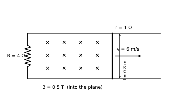
A science student notices that when she slides a copper bracelet along a railway track (treated as two parallel conducting rails separated by 0.8 m), an EMF is induced. She models the situation as follows: the two rails are connected at one end by a resistance R = 4 Ω, and a straight conducting rod of resistance r = 1 Ω slides along the rails with a constant velocity v. The region between the rails has a uniform magnetic field B = 0.5 T directed vertically downward (perpendicular to the plane of the rails). The rod moves with a velocity of 6 m/s.

(i) Name the physical principle responsible for the induced EMF in the rod. State the expression for the induced EMF in terms of B, l (length of rod = separation between rails), and v.

(ii) Calculate the induced EMF.

(iii) Calculate the current flowing through the external resistance R.

(iv) The student now doubles the velocity of the rod to 12 m/s. By what factor does the power dissipated in the external resistance R change? Justify your answer.

Diagram for question 23: Electromagnetic Induction
Show answer
(i) The principle responsible is Faraday's Law of Electromagnetic Induction.

Faraday's Law states that: the magnitude of the induced EMF in a circuit is equal to the rate of change of magnetic flux linked with the circuit.

When the rod of length l moves with velocity v perpendicular to a magnetic field B, the flux changes at the rate dΦ/dt = Blv.

∴ Induced EMF, ε = Blv

(ii) Given: B = 0.5 T, l = 0.8 m, v = 6 m/s

Using ε = Blv:

ε = 0.5 × 0.8 × 6

∴ ε = 2.4 V

(iii) The rod (internal resistance r = 1 Ω) and external resistance R = 4 Ω are in series in the circuit.

By Ohm's law, total resistance in circuit = R + r = 4 + 1 = 5 Ω

Current through the circuit:

I = ε / (R + r) = 2.4 / 5

∴ I = 0.48 A

Current through external resistance R = 0.48 A
(Since R and r are in series, the same current flows through both.)

(iv) Power dissipated in R is given by:

P = I²R = [ε / (R + r)]² × R = [Blv / (R + r)]² × R

∴ P ∝ v²

When velocity doubles (v → 2v):

P_new = [Bl(2v) / (R + r)]² × R = 4 × [Blv / (R + r)]² × R = 4P

∴ The power dissipated in R increases by a factor of 4.

Justification: Since ε = Blv, doubling v doubles the induced EMF. Current I = ε/(R+r) also doubles. Power P = I²R therefore increases by a factor of 2² = 4.
Q24Short Answer3 marks

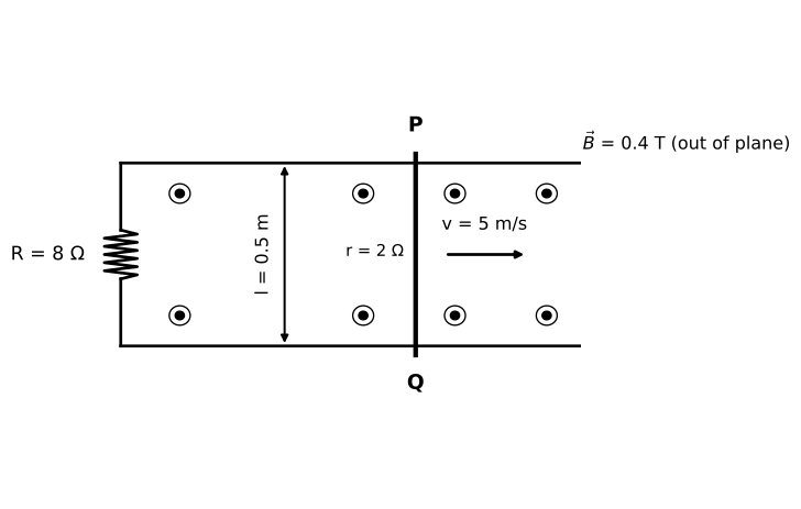
A conducting rod PQ of length 0.5 m and resistance 2 Ω is placed on two smooth, parallel conducting rails separated by 0.5 m. The rails are connected at one end by a resistor R = 8 Ω. The entire arrangement lies in a horizontal plane. A uniform magnetic field B⃗ = 0.4 T acts vertically upward (perpendicular to the plane of the rails). An external agent pushes the rod PQ with a constant velocity v = 5 m/s along the rails (away from the resistor).

(i) Calculate the EMF induced in the rod PQ.
(ii) Find the current flowing through the resistor R.
(iii) A student argues: 'Since the rod moves with constant velocity, no net force acts on it, so the external agent does no work.' Identify the flaw in this reasoning and determine the power delivered by the external agent.
(iv) If the external agent instead allows the rod to move freely (no pushing force) after giving it an initial velocity of 5 m/s, will the rod accelerate, decelerate, or move with constant velocity? Justify using Lenz's Law.

Diagram for question 24: Electromagnetic Induction
Show answer
(i) EMF Induced in Rod PQ

By Faraday's Law of Electromagnetic Induction, the EMF induced in a conducting rod of length l moving with velocity v in a magnetic field B (perpendicular to the plane of motion) is:

ε = Blv

Substituting values:
ε = 0.4 × 0.5 × 5

∴ ε = 1 V

(ii) Current Through Resistor R

The rod PQ (internal resistance r = 2 Ω) acts as a source of EMF. The resistor R = 8 Ω is connected in series with the rod's resistance.

Total resistance in circuit: R_total = r + R = 2 + 8 = 10 Ω

Total current in circuit:
I = ε / R_total = 1 / 10

∴ I = 0.1 A

Since R is the only external resistor, the same current I = 0.1 A flows through R.

(iii) Flaw in Student's Reasoning and Power Delivered by External Agent

Flaw: The student's reasoning is incorrect. Although the rod moves with constant velocity (zero acceleration), it does NOT mean zero net external force. The rod experiences a retarding force due to the magnetic braking effect (Lenz's Law) — the induced current in the rod interacts with the magnetic field, producing a force opposing its motion (F⃗ = I L⃗ × B⃗). The external agent must apply an equal and opposite force to maintain constant velocity. Therefore, the external agent continuously does work, which is entirely converted into electrical energy (and then into heat in the resistors).

Magnetic braking force on rod:
F = BIl = 0.4 × 0.1 × 0.5
F = 0.02 N

Power delivered by external agent:
P = F × v = 0.02 × 5

∴ P = 0.1 W

Verification: Total electrical power dissipated = ε × I = 1 × 0.1 = 0.1 W ✓ (Energy conservation satisfied)

(iv) Motion of Rod When External Agent is Removed (Free Motion)

By Lenz's Law: The induced current opposes the cause producing it (i.e., the change in magnetic flux). When the rod moves freely, the induced current in the rod interacts with the external magnetic field B⃗ to produce a retarding force opposing the rod's motion.

Since no external agent applies a driving force, the net force on the rod is the retarding magnetic braking force, which continuously reduces the rod's velocity. As velocity decreases, the induced EMF (ε = Blv) decreases, the current decreases, and the retarding force also decreases — but it never becomes zero as long as the rod is moving.

∴ The rod will DECELERATE (retard) continuously, approaching zero velocity asymptotically, because Lenz's Law ensures the induced effect always opposes the motion that causes it.
Q25Short Answer3 marks

A farmer in a rural area uses a small hand-cranked generator to power an LED lamp during power cuts. The generator consists of a rectangular coil of 80 turns, each of area 0.05 m², placed in a uniform magnetic field of 0.25 T. The coil is rotated at a constant angular velocity of 50π rad/s.

(i) Name the phenomenon responsible for the generation of emf in the coil. State the law that gives the direction of the induced current.

(ii) Write the expression for the instantaneous emf generated. Calculate the peak (maximum) emf produced by this generator.

(iii) If the farmer doubles the rotation speed (angular velocity) by cranking harder, how does the peak emf change? Justify your answer.

(iv) The farmer connects the generator to a pure resistor of 100 Ω. What is the average power delivered to the resistor? (Use E₀ from part (ii).)

Show answer
(i) The phenomenon responsible is Electromagnetic Induction — the generation of emf in a coil due to a change in magnetic flux through it.

Lenz's Law states that: the direction of the induced current is always such that it opposes the change in magnetic flux that caused it. (It is a consequence of the law of conservation of energy.)

(ii) By Faraday's law, for a coil rotating in a uniform magnetic field:

Instantaneous emf: E = E₀ sin ωt

where E₀ = NBAω (peak emf).

Substituting values:
N = 80, B = 0.25 T, A = 0.05 m², ω = 50π rad/s

E₀ = NBAω = 80 × 0.25 × 0.05 × 50π

E₀ = 80 × 0.25 × 0.05 × 50π
= 80 × 0.625π
= 50π

∴ E₀ = 50π ≈ 157 V

(iii) Since E₀ = NBAω, the peak emf is directly proportional to ω.

If ω is doubled (ω' = 2ω), then:
E₀' = NBA(2ω) = 2 × E₀ = 2 × 50π ≈ 314 V

∴ The peak emf doubles. This is because the rate of change of magnetic flux (dΦ/dt) doubles when the rotation speed doubles, so the induced emf (E = −NdΦ/dt) also doubles.

(iv) For a purely resistive AC circuit, the average (rms) power is:

P_avg = E₀² / (2R)

(since P_avg = E_rms² / R and E_rms = E₀/√2, so P_avg = E₀²/2R)

Substituting: E₀ = 50π V, R = 100 Ω

P_avg = (50π)² / (2 × 100) = 2500π² / 200 = 12.5π²

∴ P_avg = 12.5 × 9.87 ≈ 123 W
Q26Short Answer3 marks

A rectangular conducting loop of length 20 cm and width 10 cm, having 50 turns and resistance 40 Ω, is placed with its plane perpendicular to a uniform magnetic field B⃗. The magnetic field varies with time as B = 0.04 sin(200πt) T, where t is in seconds.

(i) Write the expression for the magnetic flux through the entire coil (all 50 turns) at any instant t.
(ii) Derive the expression for the induced emf in the coil as a function of time. What is the peak value of the induced emf?
(iii) Calculate the peak value of the induced current in the coil.
(iv) At what time t (in the first cycle) is the magnitude of the induced emf maximum? Give a physical reason for your answer.

Show answer
Given data:
Length l = 20 cm = 0.20 m, Width w = 10 cm = 0.10 m
Area of loop A = l × w = 0.20 × 0.10 = 0.02 m²
Number of turns N = 50, Resistance R = 40 Ω
B = 0.04 sin(200πt) T, so ω = 200π rad s⁻¹, B₀ = 0.04 T

─────────────────────────────────────────────────
(i) Magnetic Flux through entire coil (all N turns):

Magnetic flux linkage is defined as the total flux through all turns of the coil.

Flux through one turn: Φ₁ = B · A = 0.04 sin(200πt) × 0.02
∴ Total flux linkage NΦ = N × B × A
→ NΦ = 50 × 0.04 × 0.02 × sin(200πt)
∴ NΦ = 0.04 sin(200πt) Wb

─────────────────────────────────────────────────
(ii) Induced EMF — by Faraday's Law:

Faraday's Law of Electromagnetic Induction states that the induced emf in a coil is equal to the negative rate of change of total magnetic flux linkage:

ε = − d(NΦ)/dt

→ ε = − d/dt [0.04 sin(200πt)]
→ ε = − 0.04 × 200π × cos(200πt)

∴ ε = − 8π cos(200πt) V

The magnitude of peak (maximum) induced emf:
ε₀ = N B₀ A ω = 50 × 0.04 × 0.02 × 200π
→ ε₀ = 50 × 0.04 × 0.02 × 200π
→ ε₀ = 8π
∴ Peak emf, ε₀ = 8π ≈ 25.13 V

─────────────────────────────────────────────────
(iii) Peak Induced Current:

By Ohm's Law: I = ε / R

Peak current I₀ = ε₀ / R
→ I₀ = 8π / 40
→ I₀ = π / 5
∴ I₀ = π/5 ≈ 0.628 A

─────────────────────────────────────────────────
(iv) Time at which |ε| is maximum (first occurrence):

The induced emf is ε = −8π cos(200πt).
|ε| is maximum when |cos(200πt)| = 1, i.e., when 200πt = 0, π, 2π, …

First occurrence (t > 0): 200πt = π
→ t = π / 200π
∴ t = 1/200 = 0.005 s

Physical Reason: The induced emf is proportional to the rate of change of magnetic flux (dΦ/dt). Since B = B₀ sin(200πt), the rate of change dB/dt = B₀ × 200π × cos(200πt) is maximum when cos(200πt) = ±1, i.e., when B itself passes through zero. At t = 0.005 s, the magnetic field is zero but changing at its fastest rate — so the induced emf (and hence current) is at its peak.
Q27Short Answer3 marks

A rectangular coil of 200 turns has dimensions 10 cm × 5 cm. It is placed in a uniform magnetic field of 0.04 T such that the plane of the coil makes an angle of 30° with the direction of the magnetic field. The magnetic field is then reduced uniformly to zero in 0.02 s.
(a) Calculate the initial magnetic flux linked with the coil.
(b) Calculate the magnitude of the emf induced in the coil during this interval.
(c) If the resistance of the coil is 20 Ω, find the induced current.

Show answer
By New Cartesian (sign) convention for EMI:
Faraday's law states: The magnitude of the emf induced in a coil equals the rate of change of magnetic flux linked with it.
|e| = N |ΔΦ/Δt|

(a) Magnetic flux linked with the coil:

The magnetic flux through one turn is Φ = B A sinθ, where θ is the angle between B⃗ and the plane of the coil (i.e., complement of the angle with the normal).

Here, the plane of the coil makes 30° with B⃗, so the angle between B⃗ and the normal to the coil is (90° − 30°) = 60°.

∴ Φ = B A cosα, where α = 60° is the angle between B⃗ and the area vector (normal).

Area A = 10 cm × 5 cm = 0.10 m × 0.05 m = 5 × 10⁻³ m²

Φ = B A cos60°
= 0.04 × 5 × 10⁻³ × 0.5
= 0.04 × 5 × 10⁻³ × 0.5

∴ Φ = 1 × 10⁻⁴ Wb

(b) EMF induced:

By Faraday's law,
|e| = N |ΔΦ/Δt|

Initial flux per turn, Φᵢ = 1 × 10⁻⁴ Wb
Final flux per turn, Φ_f = 0 (B reduced to zero)
ΔΦ = Φ_f − Φᵢ = 0 − 1 × 10⁻⁴ = −1 × 10⁻⁴ Wb
Δt = 0.02 s, N = 200

|e| = 200 × (1 × 10⁻⁴) / 0.02
= 200 × 5 × 10⁻³

∴ e = 1 V

(c) Induced current:

By Ohm's law, I = e / R

I = 1 / 20

∴ I = 0.05 A
Q28Short Answer3 marks

A rectangular conducting loop of length 20 cm, width 10 cm, and having 50 turns is placed inside a long solenoid (radius 15 cm, 400 turns/m) such that the plane of the loop is perpendicular to the solenoid's axis. The solenoid is connected to a power supply that ramps its current linearly from 0 A to 8 A in 40 ms. The loop has a total resistance of 2 Ω.

(i) State Faraday's law of electromagnetic induction.
(ii) Calculate the mutual inductance M between the solenoid and the rectangular loop.
(iii) Calculate the magnitude of the emf induced in the rectangular loop.
(iv) The power supply malfunctions and instead delivers a current i(t) = 4 sin(100πt) A. Determine the maximum current induced in the loop.

(Take π² = 10, μ₀ = 4π × 10⁻⁷ T m A⁻¹)

Show answer
(i) Faraday's Law states that: the magnitude of the emf induced in a conducting loop is equal to the rate of change of magnetic flux linked with the loop.
∴ E = −dΦ/dt (for N turns, E = −N dΦ/dt)
[½ mark for statement; ½ mark for formula]

(ii) Finding Mutual Inductance M:

The magnetic field inside the solenoid (using Ampere's law) is:
B = μ₀ n I, where n = 400 turns/m

The flux linked with ONE turn of the rectangular loop lies entirely inside the solenoid (since loop area < solenoid cross-section).
Area of rectangular loop: A_loop = 0.20 × 0.10 = 2 × 10⁻² m²

Flux through the N-turn loop due to solenoid current I:
Φ_total = N × B × A_loop = N × μ₀ n I × A_loop

By definition of mutual inductance: M = Φ_total / I
∴ M = N μ₀ n A_loop

Substituting values:
M = 50 × (4π × 10⁻⁷) × 400 × (2 × 10⁻²)
M = 50 × 4π × 10⁻⁷ × 400 × 2 × 10⁻²
M = 50 × 400 × 2 × 4π × 10⁻⁹
M = 40000 × 4π × 10⁻⁹ [but 50×400×2 = 40000]
M = 4π × 40000 × 10⁻⁹
M = 1.6π × 10⁻⁴ H
M = 1.6 × 3.14 × 10⁻⁴ ≈ 5.0 × 10⁻⁴ H

∴ M ≈ 5.0 × 10⁻⁴ H
[1 mark]

(iii) Induced emf during linear ramp (0 → 8 A in 40 ms):

By Faraday's law using mutual inductance: |E| = M |dI/dt|

dI/dt = (8 − 0) / (40 × 10⁻³) = 8 / 0.040 = 200 A s⁻¹

|E| = M × (dI/dt)
|E| = 5.0 × 10⁻⁴ × 200

∴ |E| = 0.10 V (= 100 mV)
[1 mark]

(iv) Maximum induced current when i(t) = 4 sin(100πt) A:

The induced emf is: E = −M dI/dt
I(t) = 4 sin(100πt)
dI/dt = 4 × 100π cos(100πt) = 400π cos(100πt) A s⁻¹

Maximum value of dI/dt: (dI/dt)_max = 400π A s⁻¹

∴ E_max = M × 400π
E_max = 5.0 × 10⁻⁴ × 400π
E_max = 0.2π V

Maximum induced current in the loop:
I_max = E_max / R = (0.2π) / 2 = 0.1π A

Using π² = 10 → π ≈ √10 ≈ 3.16
∴ I_max = 0.1 × 3.16 ≈ 0.314 A

∴ Maximum induced current I_max = 0.1π ≈ 0.314 A
[1 mark]
Q29Short Answer3 marks

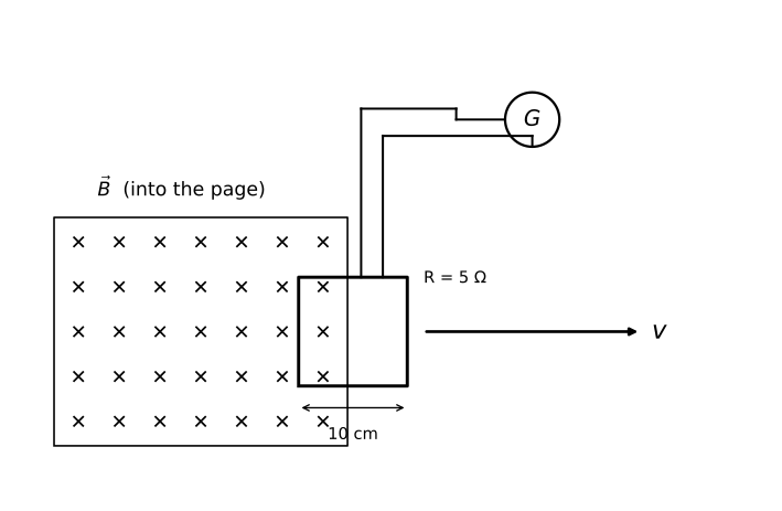
A square conducting loop of side 10 cm and resistance 5 Ω is placed in a uniform magnetic field B⃗ directed perpendicular to the plane of the loop. The loop is connected to a sensitive galvanometer. A student pulls the loop out of the magnetic field region in such a way that the current through the galvanometer varies with time as shown below:

| t (s) | I (mA) |
|--------|--------|
| 0 | 8 |
| 1 | 6 |
| 2 | 4 |
| 3 | 2 |
| 4 | 0 |

The current decreases linearly from 8 mA at t = 0 s to 0 at t = 4 s.

(a) Calculate the total charge that flows through the galvanometer as the loop is completely pulled out.
(b) Calculate the change in magnetic flux through the loop.
(c) Determine the magnitude of the uniform magnetic field B.
(d) If the same loop were pulled out in half the time (2 s instead of 4 s), how would the total charge that flows through the galvanometer change? Justify your answer.

Diagram for question 29: Electromagnetic Induction
Show answer
MARKING SCHEME (4 marks: 1+1+1+1)

(a) Total charge that flows through the galvanometer:

By Faraday's and Ohm's laws, the charge flowing is:

q = ΔΦ / R = ∫I dt

Since the current decreases linearly from 8 mA to 0 over 4 s, the I–t graph is a straight line (a triangle).

q = Area under I–t graph = ½ × base × height

q = ½ × 4 s × 8×10⁻³ A

∴ q = 16×10⁻³ C = 1.6×10⁻² C

━━━━━━━━━━━━━━━━━━━

(b) Change in magnetic flux through the loop:

Using the relation: q = ΔΦ / R

ΔΦ = q × R

ΔΦ = 1.6×10⁻² C × 5 Ω

∴ ΔΦ = 8×10⁻² Wb = 0.08 Wb

━━━━━━━━━━━━━━━━━━━

(c) Magnitude of the uniform magnetic field B:

Initially the loop is fully inside the field, so the initial flux:

Φ_initial = B × A = B × (0.10)² = 0.01 B

When fully removed, Φ_final = 0.

Therefore: ΔΦ = Φ_initial − Φ_final = 0.01 B

0.01 B = 0.08 Wb

B = 0.08 / 0.01

∴ B = 8 T

━━━━━━━━━━━━━━━━━━━

(d) Effect on total charge if the loop is pulled out in 2 s instead of 4 s:

Using q = ΔΦ / R:

The total charge q depends only on the total change in flux ΔΦ and the resistance R — it does NOT depend on the time taken.

Since ΔΦ and R remain unchanged, the total charge will remain the same (q = 1.6×10⁻² C).

However, the induced EMF and the instantaneous current will be larger (rate of change of flux is higher), but the total charge flowing through the circuit is independent of the speed of withdrawal.
Q30Short Answer3 marks

A conducting rectangular loop of dimensions 40 cm × 25 cm and resistance 8 Ω is placed in the x-y plane. A spatially uniform but time-varying magnetic field B⃗ = B₀(1 + 3t²) k̂ T exists in the region, where B₀ = 0.5 T and t is in seconds.

(i) Determine the magnetic flux linked with the loop at t = 2 s.
(ii) Calculate the magnitude of the induced EMF in the loop at t = 2 s.
(iii) Find the magnitude of the induced current in the loop at t = 2 s. State the direction of this current (clockwise or anticlockwise when viewed from +z direction) and justify it using Lenz's law.
(iv) If the loop is now physically rotated about its own central axis (parallel to y-axis) by 60° from the x-y plane (so that the normal to the loop now makes 60° with B⃗), keeping all other conditions the same, will the induced EMF at t = 2 s increase, decrease, or remain the same compared to part (ii)? Give a reason without solving numerically.

Show answer
Given: l = 40 cm = 0.40 m, b = 25 cm = 0.25 m, R = 8 Ω, B⃗ = B₀(1 + 3t²) k̂ T, B₀ = 0.5 T, t = 2 s.
Area of loop: A = 0.40 × 0.25 = 0.10 m².

(i) Magnetic flux at t = 2 s:
By definition, magnetic flux Φ = B⃗ · A⃗ = BA cos θ, where θ = 0° (normal to loop is along k̂, parallel to B⃗).
∴ Φ = B₀(1 + 3t²) × A
= 0.5 × (1 + 3 × 4) × 0.10
= 0.5 × 13 × 0.10
∴ Φ = 0.65 Wb

(ii) Induced EMF at t = 2 s:
By Faraday's law of electromagnetic induction: the induced EMF is
ε = −dΦ/dt
Φ = B₀A(1 + 3t²)
→ dΦ/dt = B₀A × 6t
At t = 2 s:
|ε| = B₀ × A × 6t = 0.5 × 0.10 × 6 × 2
∴ |ε| = 0.60 V

(iii) Induced current at t = 2 s:
By Ohm's law: I = |ε|/R
= 0.60/8
∴ I = 0.075 A

Direction (Lenz's law): Since B⃗ is directed along +z (out of the x-y plane) and B is increasing with time (dB/dt = 6B₀t > 0), the flux through the loop in the +z direction is increasing.
By Lenz's law, the induced current must oppose this increase — it must create a magnetic field in the −z direction (into the plane) inside the loop.
Using the right-hand rule, a field in the −z direction inside the loop requires the induced current to flow clockwise when viewed from the +z direction.
∴ The induced current is clockwise (viewed from +z direction).

(iv) Effect of rotating the loop by 60°:
When the loop is rotated so that its normal makes 60° with B⃗:
Φ = BA cos 60° = BA × (1/2).
The induced EMF becomes:
|ε'| = dΦ/dt = (1/2) × B₀A × 6t
This is half the value obtained in part (ii).
∴ The induced EMF will decrease (to half its earlier value).
Reason: The rate of change of flux is dΦ/dt = d(BA cos 60°)/dt = cos 60° × (dB/dt × A). Since cos 60° = 0.5 < 1 = cos 0°, the rate of change of flux — and hence the induced EMF — is smaller when the loop is tilted. The EMF depends on the component of the changing B⃗ perpendicular to the plane of the loop (i.e., along the normal), which reduces when the loop is rotated away from its original position.

Want unlimited practice on Electromagnetic Induction?

The full ClearSteps bank has 37+ reviewed questions on this chapter alone — with step-wise solutions, difficulty levels, and progress tracking. Verify your WhatsApp number and your free trial starts right here.

CBSE · CLASS 12
🎟️14-day free trial · code PRAC auto-applied
Mobile Number
+91
OTP will be sent to your WhatsApp

⭐ Trusted by 12,000+ students across India

Electromagnetic Induction Class 12 Physics Questions